
Component location table
- Make
- Land Rover
- Model
- Discovery Electrical Troubleshooting Manual
- Year
- 1995
- Section
- Page › Component location table
COMPONENT LOCATION TABLE
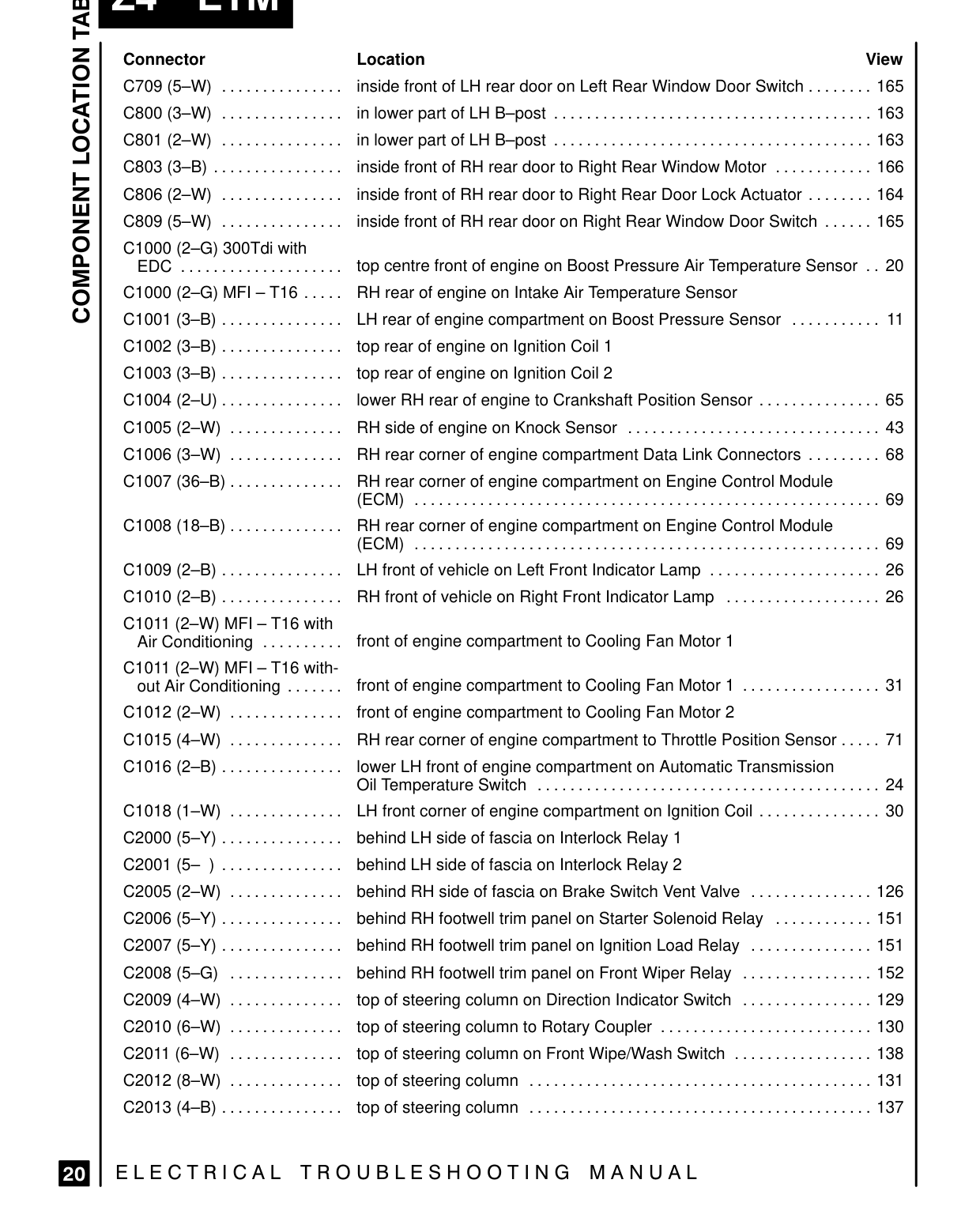
at Z | Connector Location C709 (5-W) ............... inside front of LH rear door on Left Rear Window Door Switch ........ 165 C800 (3-W) ............... inlowerpartof LHB—post ................cciiiiiiiiiiiina...... C801 (2-W) ............... inlowerpartof LHB—post .................cciiiiiiiiiia...... C803 (3-B) ................ inside front of RH rear door to Right Rear Window Motor ............ 166 pd C806 (2-W) ............... inside front of RH rear door to Right Rear Door Lock Actuator ........ 164 C809 (5-W) ............... inside front of RH rear door on Right Rear Window Door Switch ...... 165 O | C1000 (2-G) 300Tdi with EDC .................... top centre front of engine on Boost Pressure Air Temperature Sensor .. 20 C1000 (2-G) MFI -T16 ..... RH rear of engine on Intake Air Temperature Sensor Oo C1001 (3-B)............... LH rear of engine compartment on Boost Pressure Sensor ........... 11 toprear of engine on Ignition Coil 1 C1002 (3-B)............... top rear of engine on Ignition Coil 2 C1003 (3-B)............... C1004 (2-U)............... lower RH rear of engine to Crankshaft Position Sensor ............... 65 C1005 (2-W) RH side of engine on Knock Sensor ...............................
C1006 (3-W) .............. RHrear corner of engine compartment Data Link Connectors ......... 68
C1007 (36-B) .............. RHrear corner of engine compartment on Engine Control Module
C1008 (18-B).............. RHrear corner of engine compartment on Engine Control Module
C1009 (2-B) ............... LH front of vehicle on Left Front IndicatorLamp ..................... C1010 (2-B) ............... RH front of vehicle on Right Front Indicator Lamp ................... C1011 (2-W) MFI — T16 with Air Conditioning front of engine compartment to Cooling Fan Motor 1
C1011 (2-W) MFI — T16 withfront of engine compartment to Cooling Fan Motor 1 ................. 31 out Air Conditioning ....... front of engine compartment to Cooling Fan Motor 2 C1012 (2-W) ..............
C1015 (4-W) RHrear corner of engine compartment to Throttle Position Sensor ..... 71
C1016 (2-B) ............... lower LH front of engine compartment on Automatic Transmission Oil Temperature Switch ............ C1018 (1-W) .............. LH front corner of engine compartment on Ignition Coil ............... 30 behind LH side of fascia on Interlock Relay 1 C2000 (5-Y) ............... behind LH side of fascia on Interlock Relay 2 C2001 (5—
C2005 (2-W) .............. behind RH side of fascia
C2006 (5-Y)............... behind RH footwell trim panel on Starter Solenoid Relay
C2007 5-Y) ............... behind RH footwell trim panel on Ignition Load Relay
C2008 (5G) behind RH footwell trim panel on Front Wiper Relay
C2009 (4-W) .............. top of steering column on Direction Indicator Switch C2010 (6-W) .............. top of steering column to Rotary Coupler .......................... 130 C2011 (6=W) top of steering column on Front Wipe/Wash Switch ................. 138
C2012 (8-W) .............. topofsteeringcolumn
C2013 (4-B)............... topofsteeringcolumn
20 ELECTRICAL TROUBLESHOOTING MANUAL
View
163 163
43
26 26
i ii. 24
on Brake Switch Vent Valve ............... 126 ............ 151
............... 151
................ 152
................ 129
............. iii 131
137 ........... iii
Parts & tools for this job For 1995 Land Rover Discovery
- TOOLTorque wrenchSearch: 3/8 inch torque wrench
- TOOLSocket setSearch: socket set metric
- BOOKHaynes manualSearch: Haynes manual Land Rover Discovery
Links open Amazon search results in a new tab. As an Amazon Associate I earn from qualifying purchases.