
Power mirrors – circuit diagram
- Make
- Land Rover
- Model
- Discovery Electrical Troubleshooting Manual
- Year
- 1995
- Section
- Circuit diagram › Power mirrors – circuit diagram
POWER MIRRORS – CIRCUIT DIAGRAM
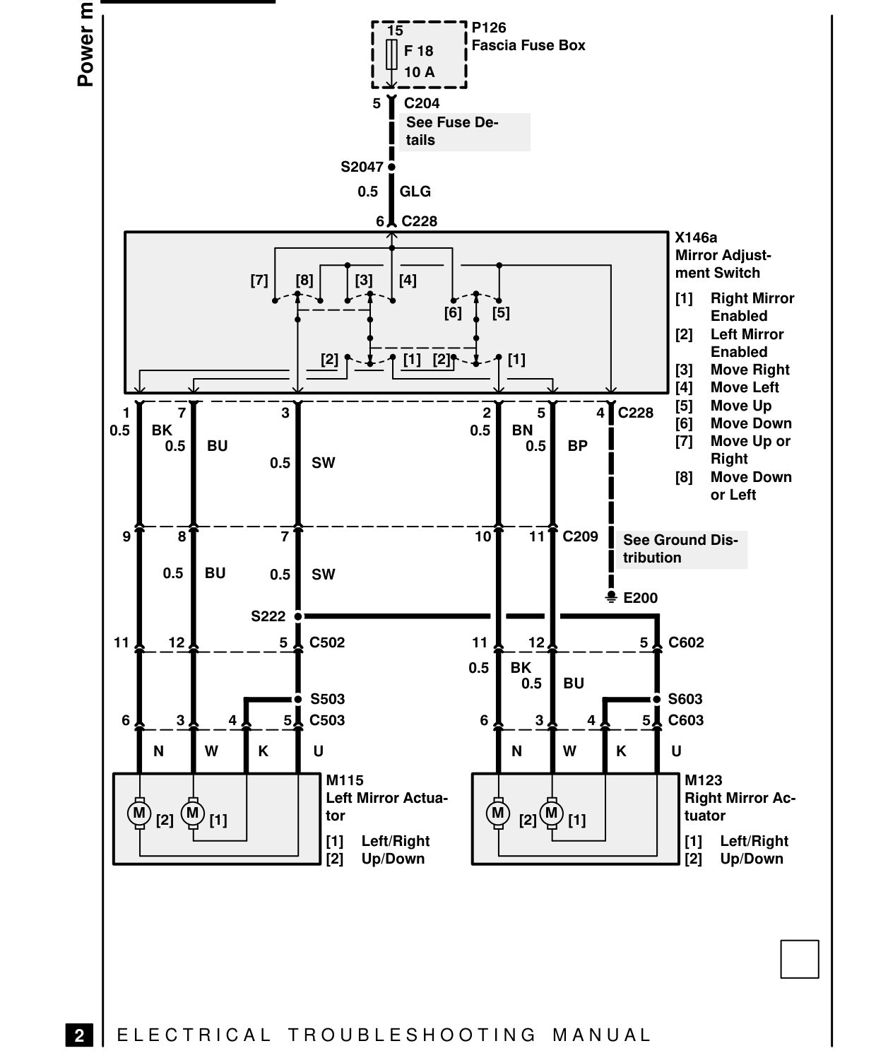
r35 ! I F18 Lea 5 | C204 | See Fuse De-
$2047 ® 0.5 [eo 6A
Telrairoel _12 [=3| [1] [2]
oY TTT TTT 05 | BK 0.5] BU 05] SW
of ef ~~ 7f = 0.5 | BU 0.5] SW
S222 oo mmmm—— — 111A 12A ~~ 5AC502
e S503
6A 3A 4A S5AC503
(Wm) Gu tor M115 Left Mirror Actua-
[11 Left/Right Up/Down
EJ | ELECTRICAL TROUBLESHOOTING MANUAL
TP126 Fascia Fuse Box T10A
tails
C228 X146a Mirror Adjustment Switch Right Mirror [61 { Enabled Left Mirror Enabled Move Right Move Left aYc22s Move Up 0.5] BN [6] Move Down 0501 BP Move Up or Right [81 Move Down or Left
1] 11Jc20 | See Ground Dis| tribution
2 E200
1284 ~~ 5A C602 111A 0.5 J BK 0.5 | BU ® S603
6A 3A 4A 5ACe603
(Wm) Gu tuator M123 Right Mirror Ac-
[11 Left/Right Up/Down
Parts & tools for this job For 1995 Land Rover Discovery
- TOOLDigital multimeterSearch: automotive digital multimeter
- PARTAssorted fuse kitSearch: car fuse assortment kit
- TOOLWire crimper and connector kitSearch: wire crimper connector kit
Links open Amazon search results in a new tab. As an Amazon Associate I earn from qualifying purchases.