
Ignition Coils
- Make
- Land Rover
- Model
- Freelander System Description and Operation (UK)
- Section
- Siemens (NAS) – description and operation › Ignition Coils
The material of the sensing element only becomes active at a temperature of approximately 300 °C (570 °F). To shorten the warm up time and minimise the emissions from a cold start and low load conditions, each HO2S contains a heating element powered by a supply from the main relay. The earth paths for the heating elements are controlled by the ECM. On start up, the current supplied to the heating elements is increased gradually to prevent sudden heating from damaging the ceramic coating. After the initial warm up period the ECM modulates the earth of the heating elements, from a map of engine speed against mass air flow, to maintain the HO2S at the optimum operating temperature.
The nominal resistance of the heating elements is 6 Ω at 20 °C (68 °F).
If an HO2S fails, the ECM illuminates the MIL. If a front HO2S fails the ECM also adopts open loop fuelling and catalytic converter monitoring is disabled. If a rear HO2S fails, catalytic converter and front HO2S monitoring is disabled.
Knock Sensors
| M19 2840 |
The knock sensors enable the ECM to operate the engine at the limits of ignition advance, for optimum efficiency, without combustion knock damaging the engine. The ECM uses two knock sensors, one for each cylinder bank, located between the cylinder banks on cylinders 3 and 4.
The knock sensors consist of piezo ceramic crystals that oscillate to create a voltage signal. During combustion knock, the frequency of crystal oscillation increases, which alters the signal output to the ECM. The ECM compares the signal to known signal profiles in its memory. If the onset of combustion knock is detected the ECM retards the ignition timing for a number of cycles. When the combustion knock stops, the ignition timing is gradually advanced to the original setting.
The knock sensor leads are of different lengths to prevent incorrect installation.
Ignition Coils
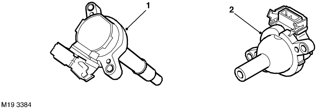
1 RH bank ignition coil
2 LH bank ignition coil
Parts & tools for this job For Land Rover Freelander
- PARTSpark plugsSearch: Land Rover Freelander spark plugs
- TOOLSpark plug socketSearch: spark plug socket
- TOOLSpark plug gap toolSearch: spark plug gap tool
Links open Amazon search results in a new tab. As an Amazon Associate I earn from qualifying purchases.