
Starting and charging – circuit diagram
- Make
- Land Rover
- Model
- Range Rover Classic Electrical Troubleshooting Manual
- Year
- 1995
- Section
- Circuit diagram › Starting and charging – circuit diagram
Starting and chargingStarting and charging – circuit diagram
STARTING AND CHARGING – CIRCUIT DIAGRAM
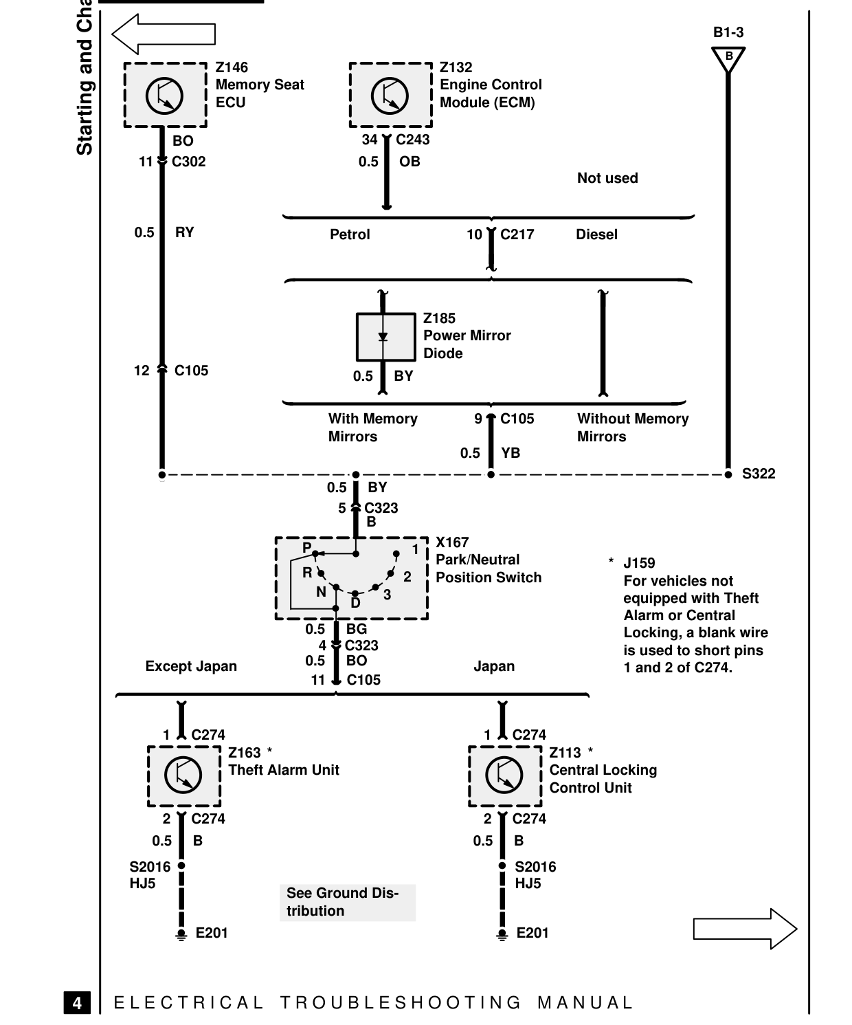
Starting and Charging Z146 Memory Seat ECU
34 BO 11 C302 0.5
0.5 RY Petrol
12 C105 0.5
With Memory Mirrors
0.5 BY 5 C323 B P R N 3 D 0.5 BG 4 C323 0.5 BO Except Japan 11 C105
1 C274 Z163 * Theft Alarm Unit
2 C274 0.5 B S2016 HJ5 See Ground Dis- tribution E201
E L E C T R I C A L T R O U B L E S H O O T I N G
4
B1-3 B Z132 Engine Control Module (ECM)
C243 OB Not used
10 C217 Diesel
Z185 Power Mirror Diode BY
9 C105 Without Memory Mirrors 0.5 YB S322
X167 1 Park/Neutral * J159 2 Position Switch For vehicles not equipped with Theft Alarm or Central Locking, a blank wire is used to short pins Japan 1 and 2 of C274.
1 C274 Z113 * Central Locking Control Unit
2 C274 0.5 B S2016 HJ5
E201
M A N U A L
Parts & tools for this job For 1995 Land Rover Range Rover
- TOOLBattery testerSearch: car battery tester
- TOOLDigital multimeterSearch: automotive digital multimeter
- TOOLBattery terminal cleanerSearch: battery terminal cleaner
Links open Amazon search results in a new tab. As an Amazon Associate I earn from qualifying purchases.