
1.3. Engine — Assembly (page 2 of 3)
- Make
- Peugeot
- Model
- J5 Pocket Mechanic, 1.8 and 2.0 petrol
- Year
- 1987–1994
- Section
- Engine assembly
the following description it is assumed that all sub-assemblies have been overhauled or replaced, as necessary.
Carefully clean the cylinder block, paying particular attention to the crevaces which are easily overlooked.
Lubricate each rotating or moving part BEFORE it is assembled. Lubricating it after the assembly has little purpose, as the oil cannot reach the gliding surfaces at all times. Oil seals should be replaced as a matter of course. The same goes for the lock washers and lock plates. Check that all oilways are thoroughly clean.
Refer to the technical data to check important dimensions before parts are re-used. In doubt it is always better to replace a part.
Assemble the engine in the following general order, referring to particular sections as indicated for individual details:
- Check the protrusion of the cylinder liners before assembly of the engine. The liners are fitted with paper gaskets or steel shims at their bottom ends, which govern the fitted position of the liners. In most cases you will find that the installation height is correct, should however, be checked. Note that either paper gaskets or steel shims are used, depending on the year of production. Proceed as follows during the measurement:
- Insert the cylinder liners without gaskets into the cylinder block. Make sure that the marks in liner and cylinder block bore are opposite each other. Push each liner fully home.
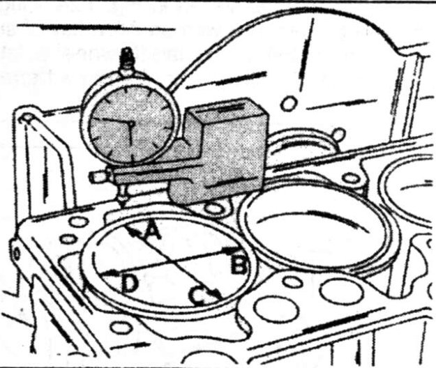
- Measure the protrusion of each liner as shown in Fig. 1.25, using the gauge shown. First place the stylus at points A to D against the cylinder block face and write down each dimension. Then place the stylus against the edge of the liner at positions A to D in Fig. 1.26, again writing down the dimension. Compare the value obtained for each point The difference between the first and the second measurement must not exceed 0.07 mm. If this is the case, there may be some foreign matter between the liner and the liner seating. Remove the liner and check.
Before proceeding with the operation note the following:
- The cylinder liners must protrude by 0.07 to 0.14 mm above the cylinder block face in the case of engines produced to April 1989, with the liner seal fitted. Always try to obtain the 0.14 mm value. On engines produced after the date given above, the protrusion has been reduced to 0.03 - 0.10 mm. Again the higher value should be considered.
- Liner seals are made of different material, depending on the year of production of the engine. Up to July 1985 they were made of paper and white, synthetic fibre material. From July 1985 steel shims with aluminium coating are used.
Parts & tools for this job For 1987 Peugeot J5
- PARTEngine gasket setSearch: Peugeot J5 1987 engine gasket set
- TOOLTorque wrenchSearch: 3/8 inch torque wrench
- TOOLFeeler gauge setSearch: feeler gauge set
Links open Amazon search results in a new tab. As an Amazon Associate I earn from qualifying purchases.