
Electrical (System components): Description and operation
- Make
- Rover
- Model
- 600 Repair Manual Supplement
- Year
- 1993–1999
- Section
- Description and operation › System components
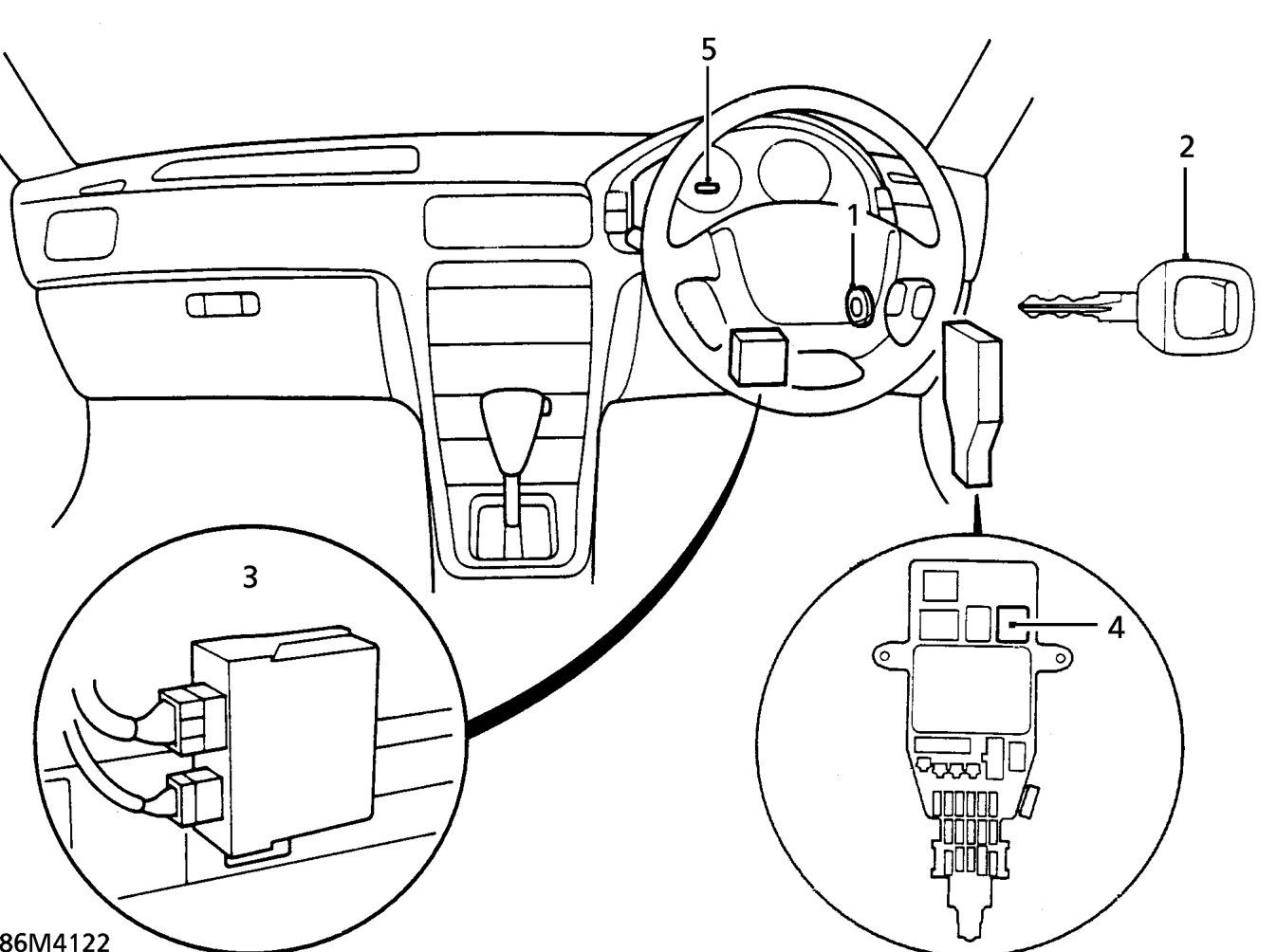
System components
- Immobilisation antenna
- Transponder in BLACK key.
- Immobilisation control unit
- Starter relay
- Immobiliser indicator light
Operation
When a correct BLACK key is inserted in the starter switch and the switch is turned to position ’II’the immobilisation control unit sends a signal to the transponder via the antenna. The transponder then sends a coded signal back through the antenna to the control unit. The control unit signals to the Engine Control Module to energise the fuel supply and energises the starter relay. The immobilisation indicator light illuminates for approx. 2 seconds to confirm that the signal from the transponder has been recognised.
The engine can now be started.
- NOTE: Due to the action of the
- immobilisation system, the engine may
- take longer than usual to start.
If an incorrect key is used, the indicator light will illuminate for 2 second and then flash continuously, and the engine will not crank.
When the starter switch is turned off, the indicator light will flash for approx. 5 seconds to signal that the immobilisation system is set correctly.
Parts & tools for this job For 1993 Rover 600
- TOOLDigital multimeterSearch: automotive digital multimeter
- PARTAssorted fuse kitSearch: car fuse assortment kit
- TOOLWire crimper and connector kitSearch: wire crimper connector kit
Links open Amazon search results in a new tab. As an Amazon Associate I earn from qualifying purchases.