
2. Slide Piston Function
- Make
- Rover
- Model
- 600 Rover 600 Repair Manual - Volumes 1 and 2 - 2nd Edition
- Section
- Brakes - ABS: operation › 2. Slide Piston Function
Brakes and ABS2. Slide Piston Function
2. Slide Piston Function
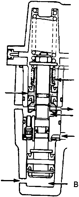
70M 0110
- A Spring
- B Chamber C
- C Slide piston
When the car is used on rough roads where the tyres sometimes lose adhesion, the anti-lock brake system may function excessively, causing a very large volume of brake fluid to flow into chamber C. When this occurs, the piston is moved excessively, resulting in an abnormal loss of pressure in the chamber B. In order to overcome this problem, the slide piston is kept in a proper position by spring force to prevent the pressure in chamber B from becoming negative.
Parts & tools for this job For Rover 600
- PARTEngine gasket setSearch: Rover 600 engine gasket set
- TOOLTorque wrenchSearch: 3/8 inch torque wrench
- TOOLFeeler gauge setSearch: feeler gauge set
Links open Amazon search results in a new tab. As an Amazon Associate I earn from qualifying purchases.