
ABS Control Unit:
- Make
- Rover
- Model
- 600 Rover 600 Repair Manual - Volumes 1 and 2 - 2nd Edition
- Section
- Brakes - ABS: operation › ABS Control Unit:
ABS Control Unit:
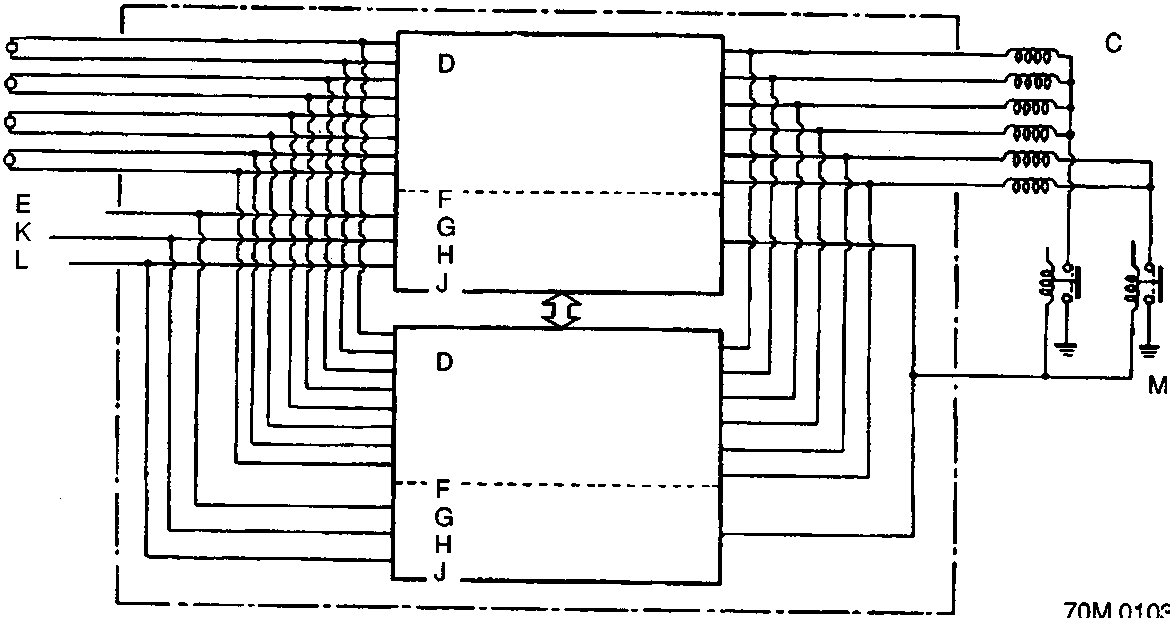
- A ABS Control unit
- B Wheel sensor
- C Solenoid valves
- D Main function
- E Pressure switch
- F Sub-function
- G Fail-safe
- H Pump motor control
- J Self-diagnosis
- K Pump motor
- L Parking brake switch
The ABS control unit consists of a main function section, which controls the operation of the anti-lock brake system, and sub-function, which controls the pump motor and "self-diagnosis."
1. Main Function
The main function section of the ABS control unit performs calculations on the basis of the signals from each wheel sensor and controls the operation of the anti-lock brake system by operating the solenoid valves in the modulator unit for each front brake and for the two rear brakes.
2. Sub-function
The sub-function section gives driving signals to the pump motor and also gives "self-diagnosis" signals, necessary for backing up the anti-lock brake system.
1. Self-Diagnostic Function
Since the anti-lock brake system modulates the braking pressure when a wheel is about to lock, regardless of the driver's intention, the system operation and the braking power will be impaired if there is a malfunction in the system. To prevent this possibility, at speeds above 10 km/h (6 mph) the self-diagnosis function, provided in the sub-function of the ABS control unit, monitors the main system functions. When an abnormality is detected, the ABS indicator light goes on. There is also a check mode of the self-diagnosis system itself; when the ignition switch is first turned on, the ABS indicator light comes on and stays on for a few seconds after the engine starts, to signify that the self-diagnosis system is functional.
2. Fail-Safe Function
When abnormality is detected in the control system by the self-diagnosis, the solenoid operations are suspended by turning off the relay (fail-safe relay) which disconnects the ground lines of all the solenoid valves to inhibit anti-lock brake system operations. Under these conditions, the braking system functions just as an ordinary one, maintaining the necessary braking function. When the ABS indicator light is turned on, it means the fail-safe is functioning.
Parts & tools for this job For Rover 600
- TOOLOBD2 scanner with ABSSearch: OBD2 scanner ABS SRS
- TOOLDigital multimeterSearch: automotive digital multimeter
Links open Amazon search results in a new tab. As an Amazon Associate I earn from qualifying purchases.