
Accumulator
- Make
- Rover
- Model
- 600 Rover 600 Repair Manual - Volumes 1 and 2 - 2nd Edition
- Section
- Brakes - ABS: operation › Accumulator
Accumulator
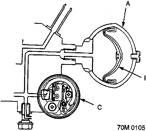
- A Accumulator
- B Bladder
- C Pressure switch
The accumulator is a pneumatic type which accumulates high-pressure brake fluid fed from the pump incorporated in the ABS pump assembly. When the anti-lock brake system operates, the accumulator and the ABS pump assembly supply high-pressure brake fluid to the modulator valve via the inlet side of the solenoid valve.
Pressure Switch
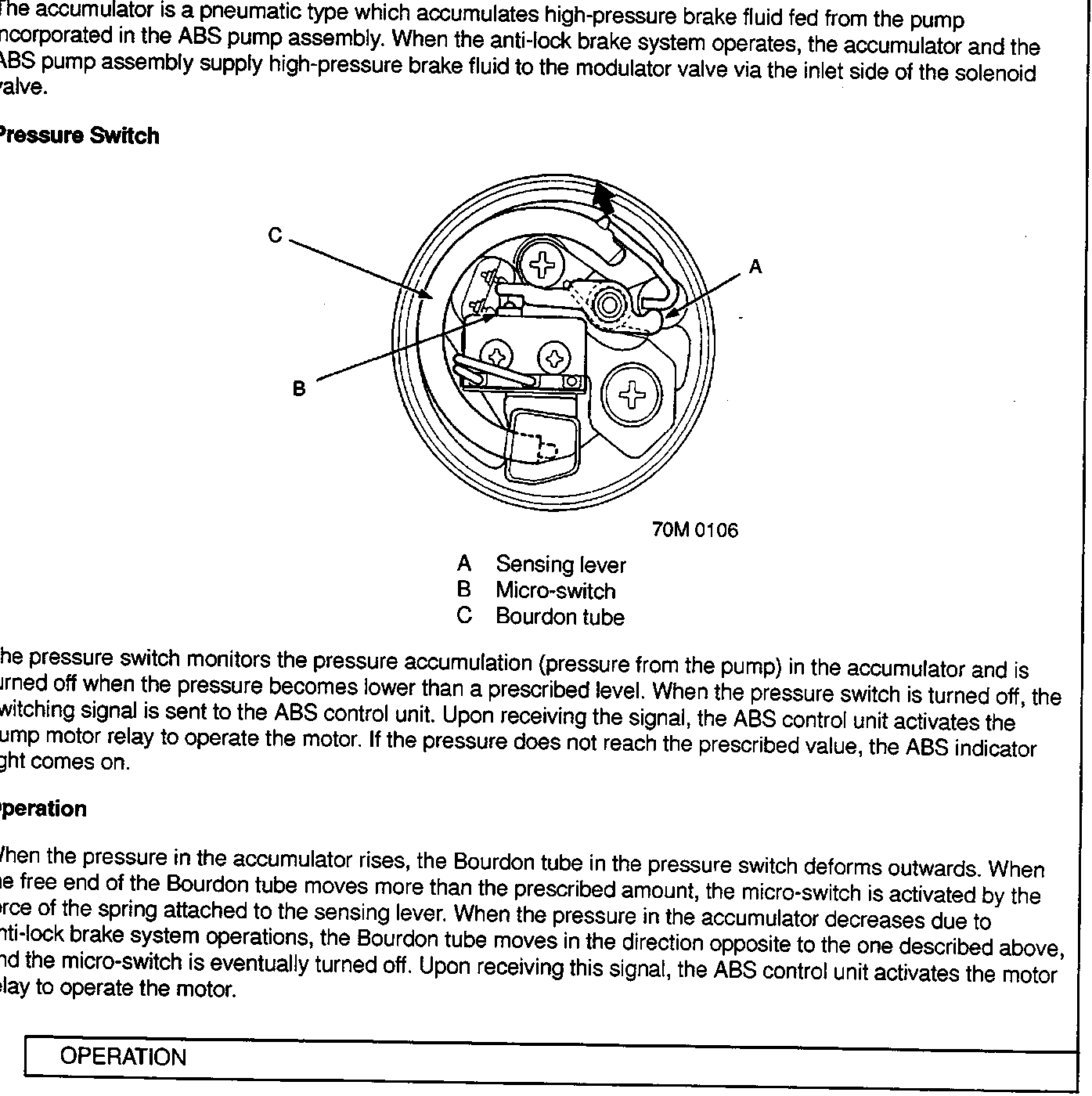
- A Sensing lever
- B Micro-switch
- C Bourdon tube
The pressure switch monitors the pressure accumulation (pressure from the pump) in the accumulator and is turned off when the pressure becomes lower than a prescribed level. When the pressure switch is turned off, the switching signal is sent to the ABS control unit. Upon receiving the signal, the ABS control unit activates the pump motor relay to operate the motor. If the pressure does not reach the prescribed value, the ABS indicator light comes on.
Operation
When the pressure in the accumulator rises, the Bourdon tube in the pressure switch deforms outwards. When the free end of the Bourdon tube moves more than the prescribed amount, the micro-switch is activated by the force of the spring attached to the sensing lever. When the pressure in the accumulator decreases due to anti-lock brake system operations, the Bourdon tube moves in the direction opposite to the one described above, and the micro-switch is eventually turned off. Upon receiving this signal, the ABS control unit activates the motor relay to operate the motor.
Parts & tools for this job For Rover 600
- TOOLOBD2 scanner with ABSSearch: OBD2 scanner ABS SRS
- TOOLDigital multimeterSearch: automotive digital multimeter
Links open Amazon search results in a new tab. As an Amazon Associate I earn from qualifying purchases.