
ABS Pump Assembly
- Make
- Rover
- Model
- 600 Rover 600 Repair Manual - Volumes 1 and 2 - 2nd Edition
- Section
- Brakes - ABS: operation › ABS Pump Assembly
ABS Pump Assembly
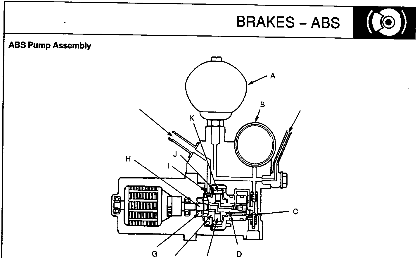
- A Accumulator
- B Pressure switch
- C Relief valve
- D Valve rod
- E Piston rod
- F Cylinder body
- G Oil seal
- H Motor shaft
- I Filter
- J Pump bearing
- K Guide
The ABS pump assembly consists of a motor, filter, guide, piston rod and cylinder body. Since a guide is positioned off-set to the centre of the motor shaft, the rotation of the motor and cylinder body provides the reciprocating motion to the piston rod. The brake fluid is thus pressurized and fed to the relief valve, accumulator and modulator.
As the pressure in the accumulator exceeds the prescribed level, the pressure switch is turned on. Approx. 0.5 seconds after receiving the ON-signal, the ABS control unit stops the motor relay operation. In this state, the pressure in the accumulator reaches 23,000 kPa (230 kg/cm², 3,270 psi).
If the pressure doesn't reach the prescribed value after the motor has operated continuously for a specified period, the ABS control unit stops the motor and activates the ABS indicator light.
Anti-lock Brake System (ABS) Indicator Light
The ABS control unit turns on the ABS indicator light when one or more of the below described abnormalities is detected. This is only a partial list.
- When the operating time of the motor in the ABS pump assembly exceeds the specified period.
- When vehicle running time exceeds 30 seconds without releasing the parking brake lever.
- When one of the rear wheels is locked during running.
- When absence of speed signals from any of the four wheel sensors is detected.
- When the activation time of all solenoids exceeds a given time or an open circuit is detected in the solenoid system.
- When solenoid output is not detected in the simulated anti-lock brake system operation carried out during running at speeds of 10 km/h (6 mph) or more.
To check the ABS indicator light bulb, the light is activated when the ignition switch is turned on. It is turned off after the engine is started if there is no abnormality in the system.
Parts & tools for this job For Rover 600
- TOOLOBD2 scanner with ABSSearch: OBD2 scanner ABS SRS
- TOOLDigital multimeterSearch: automotive digital multimeter
Links open Amazon search results in a new tab. As an Amazon Associate I earn from qualifying purchases.