
DTC 2–3
- Make
- Rover
- Model
- 600 Rover 600 Repair Manual - Volumes 1 and 2 - 2nd Edition
- Section
- Fault finding › DTC 2–3
Supplementary restraint system (SRS)DTC 2–3
DTC 2–3
WARNING: Whenever the ignition is switched ON (II), or has been turned OFF for less than 3 minutes, be careful not to bump the SRS unit; the airbags could accidentally deploy and cause damage or injury.
Test 1 – Check for short to power in passenger’s airbag inflator
- Turn ignition OFF. Disconnect battery negative and then the positive terminal and wait 3 minutes.
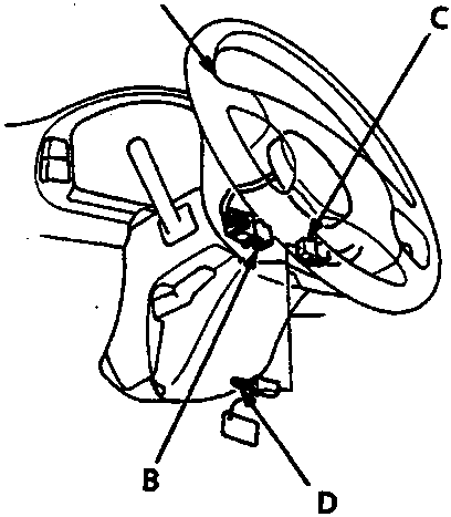
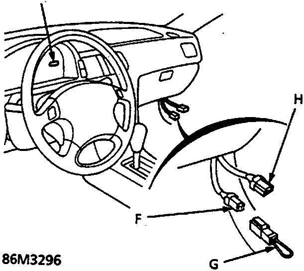
- Connect the short connector (RED) to the driver’s airbag connector.
- Connect short connector A to the SRS main harness 3 – P connector.
- Connect SCS short connector A to the service check connector.
- Reconnect battery positive and negative terminals.
- Turn ignition ON (II).
- Record the most recent DTC, is DTC 2 – 3 or DTC 2 – 3 indicated?
If DTC 2 – 3 is indicated, go to Test 2.
If DTC 2 – 2 is indicated, short to power in the passenger’s airbag inflator, replace passenger’s airbag assembly.
Test 2 – Check for voltage at connector
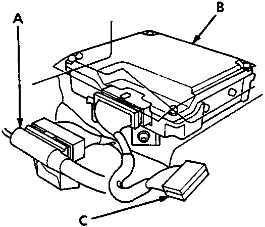
Connect Test Harness B:
- Turn ignition OFF and disconnect SCS short connector.
- Disconnect battery negative and then the positive terminal and wait 3 minutes.
| A | 1 | 2 | 3 | 4 | 5 | 6 | 7 | 8 | 9 | 10 | 11 | 12 | 13 | 14 | 15 | 16 | 17 | 18 |
|---|---|---|---|---|---|---|---|---|---|---|---|---|---|---|---|---|---|---|
| B | 1 | 2 | 3 | 4 | 5 | 6 | 7 | 8 | 9 | 10 | 11 | 12 | 13 | 14 | 15 | 16 | 17 | 18 |
86M3314
- A SRS main harness 18 – P connector
- B SRS unit
- C Test Harness B – SMD 4088
- Connect the short connector (RED) to the driver’s airbag 3 – P connector.
- Disconnect SRS main harness 18 – P connector from SRS unit and connect Test Harness B between SRS unit and the 18 – P connector.
- Reconnect the batter positive, then the negative terminal.
Connect voltmeter between No. B2 and B5 terminals of Test Harness B. - Turn ignition ON (II) and measure voltage, which should be 0.5 V or less.
Parts & tools for this job For Rover 600
- TOOLOBD2 scannerSearch: OBD2 scanner
- TOOLDigital multimeterSearch: automotive digital multimeter
- TOOLBack-probe test leadsSearch: back probe test leads
Links open Amazon search results in a new tab. As an Amazon Associate I earn from qualifying purchases.