
Test 3 – Check the SRS unit
- Make
- Rover
- Model
- 600 Rover 600 Repair Manual - Volumes 1 and 2 - 2nd Edition
- Section
- Fault finding › Test 3 – Check the SRS unit
Supplementary restraint system (SRS)Test 3 – Check the SRS unit
Test 3 – Check the SRS unit
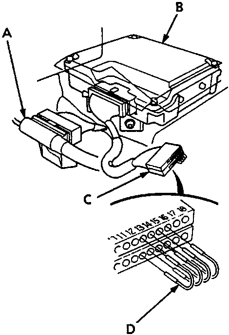
- Disconnect the SRS main harness 6 – P connector from the cable reel.
- Disconnect SRS main harness 18 – P connector from SRS unit and connect Test Harness B.
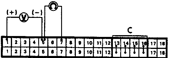
- Connect jumper wires, as shown, to No. 13, 14, 15, and 16 terminals on rows A (SRS unit) and B (main harness) of Test Harness B. Ensure jumper wires are connected to the correct terminals.
- Reconnect battery positive and negative terminals.
Connect voltmeter between terminals No. A1 (+) and No. A5 (–) of Test Harness B. - Turn ignition ON (II) and measure voltage, which should be 9.4 – 14 V.
- Turn ignition OFF.
- Measure resistance between terminals No. A7 and A5, which should be 0.75 – 1.0 ohm.
Note: The resistance will be unstable if measured immediately after the ignition is switched OFF. Allow time for the reading to stabilise.
If voltage and resistance are as specified, go to Test 4.
If voltage and resistance are not as specified, SRS unit is faulty. Replace the unit.
Test 4 – Check for open circuit in SRS main harness
- Turn ignition OFF.
- Check for continuity between terminals No. B1 and No. B7 of Test Harness B:
If there is continuity, problem corrected by reconnection. Ensure all terminals make good contact and recheck the system, see Fault Finding Intermittent Failures
If there is no continuity, open circuit in SRS main harness. Replace harness.
Parts & tools for this job For Rover 600
- TOOLOBD2 scanner with SRSSearch: OBD2 scanner ABS SRS
- TOOLTrim removal tool kitSearch: trim removal tool kit
Links open Amazon search results in a new tab. As an Amazon Associate I earn from qualifying purchases.