
DTC 1–4
- Make
- Rover
- Model
- 600 Rover 600 Repair Manual - Volumes 1 and 2 - 2nd Edition
- Section
- Fault finding › DTC 1–4
Supplementary restraint system (SRS)DTC 1–4 · page 1 of 2
DTC 1–4
WARNING: Whenever the ignition is switched ON (II), or has been turned OFF for less than 3 minutes, be careful not to bump the SRS unit; the airbags could accidentally deploy and cause damage or injury.
Test 1 – Check for short to earth in the driver’s airbag inflator:
- Turn ignition OFF. Disconnect battery negative and then the positive terminal and wait 3 minutes.
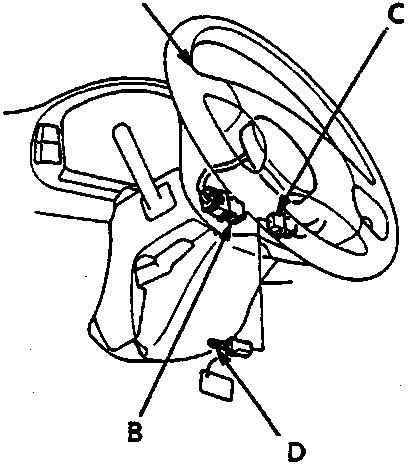
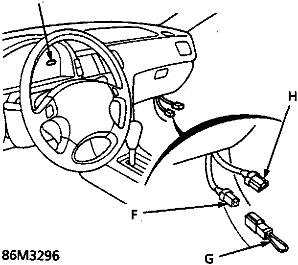
- Connect the short connector (RED) to the driver’s airbag connector.
- A
- Driver's airbag Assembly
- B
- Cable reel 3 – P connector
- C
- Short connector (RED)
- D
- SRS Short connector A – SMD 4090
- E
- SRS indicator light
- F
- Service check 2 – P connector
- G
- SCS short connector – SMD 4086
- H
- Data link connector (3 – P)
- Connect SCS short connector A to the cable reel 3 – P connector.
CAUTION: Do not disconnect the passenger’s airbag connector.
- Connect the SCS short connector to the service check connector.
- Reconnect battery positive and negative terminals.
- Turn ignition ON (II).
- Record the most recent DTC, is DTC 1 – 4 or DTC 1 – 2 indicated?
- If DTC 1 – 4 is indicated, go to Test 2.
- If DTC 1 – 2 is indicated, short to earth in driver’s airbag inflator. Replace driver’s airbag assembly.
Test 2 – Check the SRS unit
Connect Test Harness B:
- Turn ignition OFF and disconnect SCS short connector.
- Disconnect battery negative and then the positive terminal and wait 3 minutes.
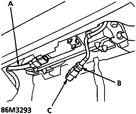
- A
- SRS main harness
- B
- Passenger's airbag 3 – P connector
- C
- Short connector (RED)
- Remove the glovebox and connect the short connector (RED) to the passenger’s airbag 3 – P connector.
- Disconnect SRS main harness 18 – P connector from SRS unit and connect Test Harness B between SRS unit and the 18 – P connector.
- Connect jumper wires, as shown, to No. 13, 14, 15, and 16 terminals on rows A (SRS unit) and B (main harness) of Test Harness B. Ensure jumper wires are connected to the correct terminals.
- Reconnect battery positive and negative terminals.
Parts & tools for this job For Rover 600
- TOOLOBD2 scannerSearch: OBD2 scanner
- TOOLDigital multimeterSearch: automotive digital multimeter
- TOOLBack-probe test leadsSearch: back probe test leads
Links open Amazon search results in a new tab. As an Amazon Associate I earn from qualifying purchases.