
DTC 1–4 (page 2 of 2)
- Make
- Rover
- Model
- 600 Rover 600 Repair Manual - Volumes 1 and 2 - 2nd Edition
- Section
- Fault finding
Supplementary restraint system (SRS)DTC 1–4 · page 2 of 2
Test 3 – Check for short to earth in cable reel
- Turn ignition OFF.
86M3303
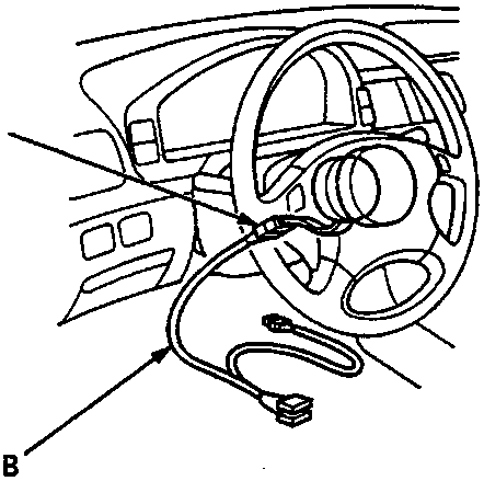
- A Cable reel 6 – P connector
- B Test Harness C – SMD 4089
- Remove dashboard lower cover and disconnect cable reel 6 – P connector from SRS main harness.
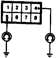
- Connect Test Harness C to the cable reel 6 – P connector.
- Check for continuity between No. 4 terminal of Test Harness C and earth, between No. 5 terminal and earth:
If there is continuity, short to earth in the cable reel. Replace cable reel.
If there is no continuity, go to Test 4.
86M3302
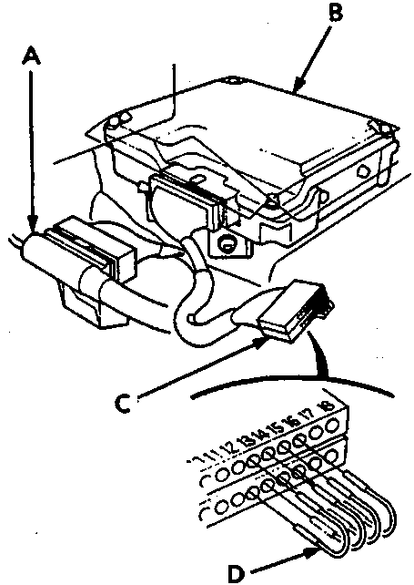
- A SRS main harness 18 – P connector
- B SRS unit
- C Test Harness B – SMD 4088
- D Jumper wires – SMD 4087
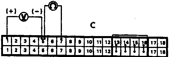
- Connect voltmeter between terminals No. A1 (+) and No. A5 (–) of Test Harness B.
- Turn ignition ON (II) and measure voltage, which should be 9.4 – 14 V.
- Connect voltmeter between terminals No. A7 and No. A5 of Test Harness B and measure voltage, which should be 0.5 V or less.
If voltage is less than 0.5 V, go to Test 3.
If voltage is more than 0.5 V, SRS unit is faulty. Replace the unit.
Parts & tools for this job For Rover 600
- TOOLOBD2 scannerSearch: OBD2 scanner
- TOOLDigital multimeterSearch: automotive digital multimeter
- TOOLBack-probe test leadsSearch: back probe test leads
Links open Amazon search results in a new tab. As an Amazon Associate I earn from qualifying purchases.