
Original page
- Make
- Rover
- Model
- 600 Rover 600 Repair Manual - Volumes 1 and 2 - 2nd Edition
- Section
- Fault finding › Original page
‹ Prev FAULT: The LED of the SRS unit does not light.Next › Test 2 – Check for open circuit in main harness or dashboard harness
Supplementary restraint system (SRS)Original page
Test 4 – Check for open circuit in SRS unit sub-harness or slip ring
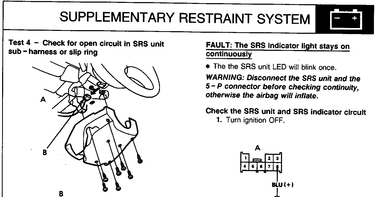
86M3274
- A View from terminal side
- B SRS main harness 5-P connector
- C View from wire side
- Disconnect SRS main harness 5-P connector from slip ring.
- Connect voltmeter between terminals No. 5 (+) of the SRS sub-harness 5-P connector and earth.
- Turn ignition ON (II).
- Measure voltage:
If there is no battery voltage, open circuit in RED wire of SRS main harness between under dash fusebox and slip ring. Replace SRS main harness.
If there is battery voltage, open circuit in RED wire of SRS unit sub-harness or the slip ring. Replace faulty component.
FAULT: The SRS indicator light stays on continuously
- The the SRS unit LED will blink once.
WARNING: Disconnect the SRS unit and the 5-P connector before checking continuity, otherwise the airbag will inflate.
Check the SRS unit and SRS indicator circuit
- Turn ignition OFF.
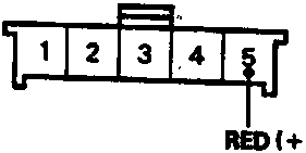
- A SRS main harness 8-P connector
- B View from wire side
- Disconnect SRS main harness 8-P connector from main harness.
- Connect voltmeter between terminal No. 8 (+) of the SRS main harness 8-P connector and earth.
- Turn ignition ON (II).
- Measure voltage for 6 seconds after the ignition is switched ON (II):
If there is more than 8.5V, go to Test 2.
If there is less than 8.5V, go to Test 3.
Original page
‹ Prev FAULT: The LED of the SRS unit does not light.Next › Test 2 – Check for open circuit in main harness or dashboard harness
Parts & tools for this job For Rover 600
- TOOLOBD2 scanner with SRSSearch: OBD2 scanner ABS SRS
- TOOLTrim removal tool kitSearch: trim removal tool kit
Links open Amazon search results in a new tab. As an Amazon Associate I earn from qualifying purchases.