
Remove
- Make
- Rover
- Model
- Coupé, Cabriolet & Tourer 200/400 Coupé, Cabriolet & Tourer Workshop Manual
- Section
- Repairs › Remove
Heating and ventilationRemove
Service Repair No. 80.20.12
Remove
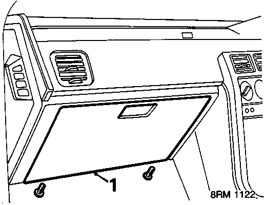
- Remove glove box lid, see BODY – Repairs.
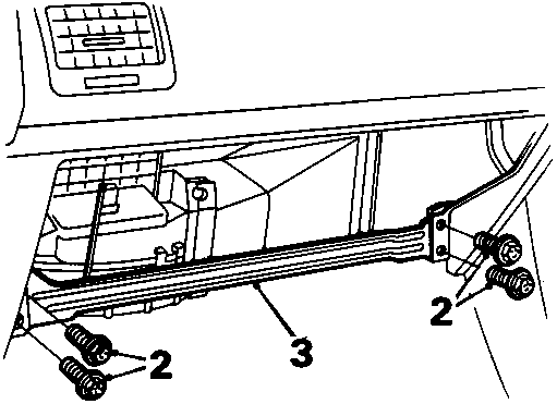
- Remove 4 bolts securing glove box rail.
- Remove glove box rail.
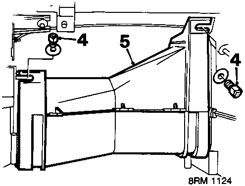
- Remove 2 bolts securing heater duct.
- Remove heater duct.
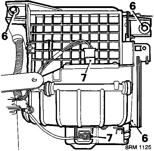
- Remove 3 bolts securing blower assembly.
- Disconnect 2 multiplugs.
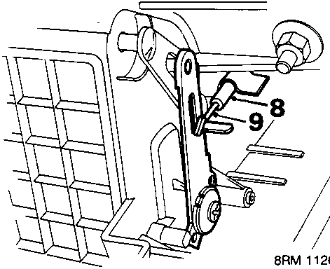
- Release recirculation outer cable from clip on blower housing.
- Release inner cable from flap lever.
- Remove blower assembly.
Refit
- Position blower assembly.
- Fit bolts securing blower assembly and tighten them to 10 Nm.
- Connect 2 multiplugs.
- Slide recirculation control lever to recirculation position.
- While holding flap in upper (closed) position connect recirculation inner cable to flap lever and secure outer cable in clip on blower housing.
- Check operation of recirculation control.
- Position heater duct.
- Fit and tighten 2 bolts securing heater duct.
- Position glove box rail.
- Fit and tighten 4 bolts to secure glove box rail.
- Refit glove box lid, see BODY – Repairs.
Parts & tools for this job For Rover Coupé, Cabriolet & Tourer
- TOOLA/C manifold gauge setSearch: AC manifold gauge set
- TOOLUV leak detection kitSearch: AC UV leak detection kit
- PARTCabin filterSearch: Rover Coupé, Cabriolet & Tourer cabin filter
Links open Amazon search results in a new tab. As an Amazon Associate I earn from qualifying purchases.