
Power unit with manual gearbox - r + r
- Make
- Alfa Romeo
- Model
- 147 Factory Service Manual
- Year
- 2000–2004
- Section
- Engine and power unit › Power unit with manual gearbox - r + r
Power unit with manual gearbox - r + r
Removing
Position the vehicle on the ramp.
Proceed with the removal - 5530B10 battery - r+r.
When removing the battery, make sure also to disconnect the starter motor supply lead, shown in the figure, from the maxi fuse box.
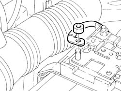
Proceed with the removal - 5530B52 Battery DRIP TRAY/SUPPORT - R.R..
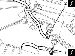
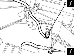
1. Disconnect the earth cable from the gearbox side rigid power unit mounting.
| Name | Connector | |
|---|---|---|
| 1 | Earth on engine | C40A |
2. Disconnect the electrical connection from the reversing light switch.
| Name | Connector | |
|---|---|---|
| 2 | Reversing lights switch | I20 |
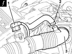
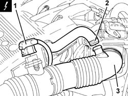
1. Disconnect the electrical connection from the air flow meter.
| Name | Connector | |
|---|---|---|
| 1 | Air flow meter | K41 |
Release the air flow meter wiring from the attachment on the air intake duct.
2. Disconnect the oil vapour recirculation pipe from the air intake duct.
3. Disconnect the air intake duct from the throttle body.
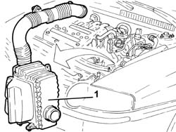
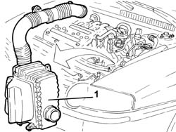
1. Remove the air filter assembly and intake duct complete with air flow meter after releasing it from the resonator unit.
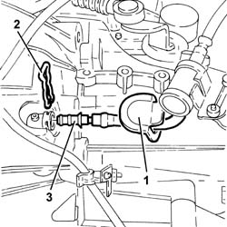
1. Move as much as necessary the rubber protection covering the clutch hydraulic actuator pipe joint.
2. Fully withdraw the spring clip securing the pipe to the actuator body.
3. Disconnect the flexible pipe from the vibration damper to the clutch hydraulic actuator, hydraulic actuator side, and secure it.
Recover the clutch fluid which comes out into a suitable container, then plug the pipe and position it to one side.
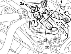
1. Disconnect the gear selector and engagement cables.
To disconnect the gear selection cable, press on the release tabs shown in the figure and move the cable backwards.
2. Remove the stop plates (2a) and release the gear selection and engagement cables from the mounting bracket (2b).
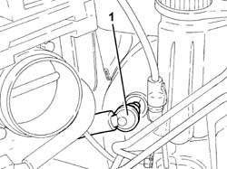
1. Disconnect the single-acting valve for the brake servo, brake servo side.
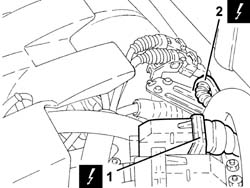
1. Disconnect the electrical connection from the fuel injection-ignition control unit.
| Name | Connector | |
|---|---|---|
| 1 | Engine management ECU | M10 |
2. Disconnect the engine front connection.
| Name | Connector | |
|---|---|---|
| 2 | Front / engine coupling | D4 |
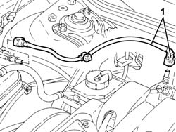
1. Disconnect the rapid attachment couplings and remove the fuel vapour recovery pipe.
Plug the fuel vapour recovery system pipes.
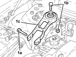
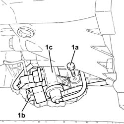
1. Undo the bolts (1a) and (1b) and remove the power unit reaction rod (1c).
Drain the power steering fluid from the reservoir using a suitable syringe.
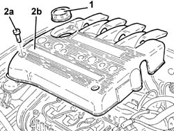
1. Undo and remove the engine oil filler cap.
2. Undo the bolts (2a) and remove the ignition coils cover (2b).
Place the engine oil filler plug back in its housing.
Discharge the fuel supply pressure with the tool connected to the specific valve located on the side of the fuel manifold pipe.
| Name | Country | |
|---|---|---|
| Rapid connector | 1.870.684.000 |
1. Disconnect the rapid attachment of the fuel supply front pipe, fuel manifold pipe side.
Plug the fuel supply front pipe and move it over to one side.
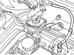
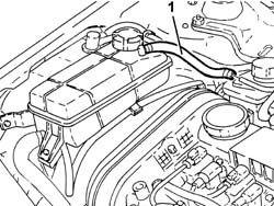
1. Disconnect the coolant return pipe to the coolant reservoir.
Plug the disconnected pipes to prevent impurities from entering the system.
Drain the air conditioner refrigerant system - 5040A10 Air conditioning refrigerant CIRCUIT - Draining and Refilling.
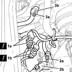
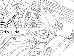
1. Disconnect the electrical connections (1a) and (1b) of the Lambda probes and release the electrical wiring from its attachments.
| Name | Connector | |
|---|---|---|
| 1a | Lambda sensor on pre-catalyzer | K15 |
| Name | Connector | |
|---|---|---|
| 1b | Lambda sensor downstream of post-catalyzer | K17 |
2. Undo the bolt (2a) and disconnect the flange (2b) of the refrigerant inlet/supply pipes from the air conditioner compressor.
3. Undo the nut (3a) and disconnect the flange (3b) of the air conditioner condenser pipe to the intermediate connector, intermediate connector side.
Seal the disconnected connectors, using suitable plugs, to prevent humidity and impurities from entering the system.
Proceed with the removal - 4450B12 front or rear wheels (two) - r+r.
Proceed with the removal - 7055B64 Engine compartment DUST shield in front wheel arch (one), left or right - R.R. (Right and left sides).
Proceed with the removal - 7055B42 Additional FRONT WHEEL ARCH (one), left or right - R.R. (Right and left sides).
1. Disconnect the lower coolant outlet hose from the radiator and drain the engine coolant.
Manually press the springs and remove the hose's rapid attachment.
Recover the coolant using a suitable container.
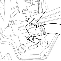
1. Disconnect the upper coolant inlet hose to the radiator.
Manually press the springs and remove the hose's rapid attachment.
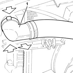
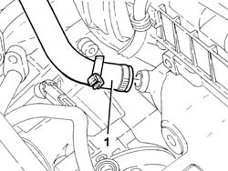
1. Disconnect the engine coolant supply pipe, water pump rigid inlet pipe side.
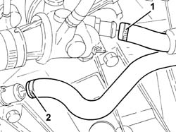
1. Disconnect the coolant return pipe to the climate control heater, thermostat side.
2. Disconnect the coolant return pipe from the climate control heater, water pump rigid inlet pipe side.
Proceed with the removal - 7210E10 R.R. FRONT BUMPER.
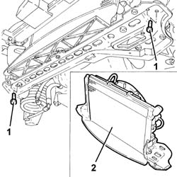
1. Undo the bolts securing the radiator bottom crossmember to the bodywork.
2. Remove the engine cooling radiator complete with fan, air conditioning condenser with pipes and bottom crossmember.
Make sure to release the fan's top pin from the relevant mounting bracket.
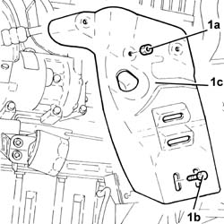
1. Undo the nuts (1a) and bolts (1b), then remove the exhaust manifold heat shield (1c).
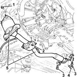
1. Undo the nuts securing the catalytic converter to the exhaust manifold.
2. Undo the nuts securing the catalytic converter to the engine sump.
3. Undo the bolts securing the catalytic converter flexible mounting brackets to the bodywork.
4. Undo the bolts securing the catalytic converter to the intermediate silencer.
5. Remove the complete catalytic converter.
Remove the gaskets.
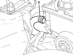
1. Disconnect the return pipe from the heat exchanger to the power steering fluid reservoir, reservoir side.
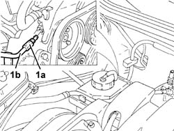
1. Undo the connector (1a) and disconnect the supply pipe from the power steering pump to the power steering box (1b), pump side.
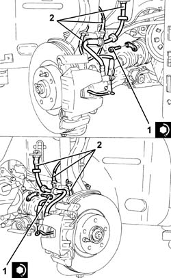
1. Unscrew the bolts securing the drive shafts to the internal differential/drive shaft
2. Release the front brake hoses, brake pad sensor wiring and ABS inductive sensor wiring from their attachments.
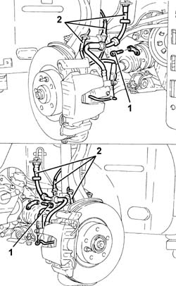
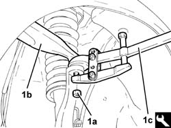
1. Undo the nuts (1a) and disconnect the front upper wishbones (1b) from the vertical links with the tool (1c).
| Name | Country | |
|---|---|---|
| 1c | Extractor | 1.821.169.000 |
Move the drive shafts away from the differential internal drive shaft/intermediate drive shaft.
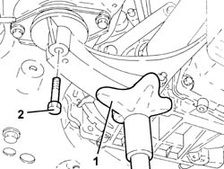
1. Position a hydraulic jack under the power unit rear rigid mounting.
2. Undo the bolt securing the power unit rear rigid mounting to the flexible mounting.
Lower the hydraulic jack slowly and remove.
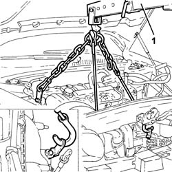
1. Using a hydraulic hoist fitted with suitable chains positioned as shown in the figure, support the power unit.
1. Undo the bolts fixing the power unit gearbox side rigid support to the flexible mounting.
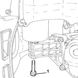
1. Undo the bolt securing the timing side rigid engine support to the flexible mounting.
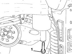
Slowly lower the power unit with the hydraulic hoist until it is resting on the ground.
Release the hydraulic hoist's chains from the power unit.
Raise the car on a lift.
1. Using the hydrualic hoist fitted with suitable chains as described above, position the power unit on a platform.
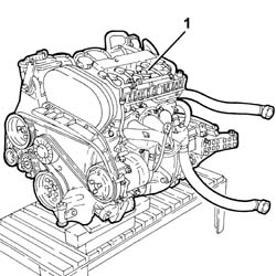
Refitting
Using a hydraulic hoist fitted with suitable chains as described above, position the power unit under the car.
Release the hydraulic hoist's chains from the power unit.
Lower the car with the lift.
Through the engine compartment, support the power unit with the hydraulic hoist fitted with suitable chains.
Slowly lift the power unit with the hydraulic hoist until it is resting in its seating in the engine compartment.
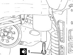
1. Tighten the bolt fixing the timing side rigid engine support to the flexible mounting to the recommended torque.
| Fastening | Component | Ø | Value (daNm) | |
|---|---|---|---|---|
| 1 | Bolt | ENGINE MOUNT TIMING SIDE | M12 | (Flexible mounting side) 7.9 ÷ 9.7 |
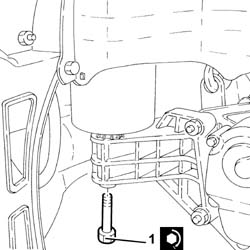
1. Tighten to the specified torque the bolt fixing the power unit gearbox side rigid support to the flexible mounting.
| Fastening | Component | Ø | Value (daNm) | |
|---|---|---|---|---|
| 1 | Bolt | POWER UNIT GEAR BOX END RIGID MOUNT | M10 | (Flexible mounting side) 4.2 ÷ 5.1 |
Release the hydraulic hoist's chains from the power unit.
1. Position a hydraulic jack under the power unit rear rigid mounting and raise it slowly until it is in contact with the relevant flexible mounting.
2. Tighten the bolt fixing the power unit rigid rear support to the flexible mounting to the recommended torque.
| Fastening | Component | Ø | Value (daNm) | |
|---|---|---|---|---|
| 2 | Bolt | POWER UNIT RIGID REAR MOUNT | M12 | (Flexible mounting side) 7.5 ÷ 9.2 |
Remove the hydraulic jack.
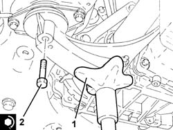
Refit the drive shafts in their seating in contact with the internal differential drive shaft/intermediate drive shaft.
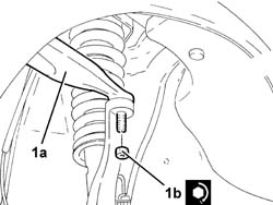
1. Connect the front upper track control arms (1a) to the steering knuckles and tighten the nuts (1b) to the specified torque.
| Fastening | Component | Ø | Value (daNm) | |
|---|---|---|---|---|
| 1b | Nut | FRONT SUSPENSION TOP LEVER | M10 | (Steering knuckle side) 4.3 ÷ 4.7 |
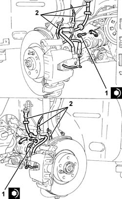
1. Tighten the bolts securing the drive shafts to the differential internal drive shaft/intermediate drive shaft to the specified torque.
| Fastening | Component | Ø | Value (daNm) | |
|---|---|---|---|---|
| 1 | Bolt | DRIVESHAFT | M8 | (Differential. internal. driveshaft./side..) 3.5 ÷ 4.3 |
2. Secure the front brake hoses, brake pad wear wiring and BAS inductive sensor wiring.
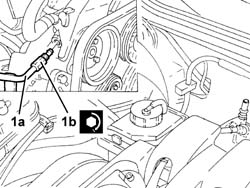
1. Connect the supply pipe from power steering pump to power steering box (1a), pump side, and tighten the connector (1b) to the specified torque.
| Fastening | Component | Ø | Value (daNm) | |
|---|---|---|---|---|
| 1b | Connector | PIPE BTWN PUMP + POWER STEERING BOX | M16 | (Power assisted steering pump side) 4.5 ÷ 5.5 |
Connect the return pipe from the heat exchanger to the power steering fluid reservoir, reservoir side.
1. Refit the catalytic converter in its seat complete with gaskets.
2. Tighten, to the specified torque, the bolts securing the catalytic converter to the intermediate silencer.
| Fastening | Component | Ø | Value (daNm) | |
|---|---|---|---|---|
| 2 | Bolt | CATALYTIC CONVERTER (ONE) | M8 | (Intermediate silencer side) 2.7 ÷ 3.3 |
3. Tighten the bolts securing the catalytic converter flexible mounting brackets to the bodywork.
4. Tighten the nuts securing the catalytic converter mounting to the engine sump.
5. Tighten, to the specified torque, the nuts securing the catalytic converter to the exhaust manifold.
| Fastening | Component | Ø | Value (daNm) | |
|---|---|---|---|---|
| 5 | Nut | CATALYTIC CONVERTER (ONE) | M10 | (Manifold side) 4.1 ÷ 5.0 |
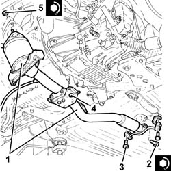
Place the exhaust manifold heat shield back in its housing and fix it using the nuts.
Place back in its housing the engine cooling radiator, complete with fan, air conditioning condenser with pipes and bottom crossmember.
Check that the fan's top pin is fitted correctly in its mounting bracket.
Tighten the bolts securing the radiator bottom crossmember to the bodywork.
Proceed with the refitting - 7210E10 R.R. FRONT BUMPER.
Connect the coolant return hose from the climate control heater on the side of the rigid inlet pipe to the water pump.
Connect the coolant supply pipe to the climate control heater, thermostat side.
Connect the engine coolant supply pipe, water pump rigid inlet pipe side.
Connect the upper coolant inlet hose to the radiator.
Connect the lower coolant outlet hose from the radiator.
Proceed with the removal - 7055B42 Additional FRONT WHEEL ARCH (one), left or right - R.R. (Right and left sides).
Proceed with the removal - 7055B64 Engine compartment DUST shield in front wheel arch (one), left or right - R.R. (Right and left sides).
Proceed with the refitting - 4450B12 front or rear wheels (two) - r+r.
1. Connect the flange of the pipe from the air conditioner condenser to the intermediate connector (1a), intermrediate connector side, and tighten the nut (1b) to the specified torque.
Replace the O-Ring seals for the connectors. Only use green coloured seals, resistant to R134A coolant fluid. Lubricate the threads of the connectors using anti-freeze.
| Fastening | Component | Ø | Value (daNm) | |
|---|---|---|---|---|
| 1b | Nut | COOLANT SYSTEM FITTINGS | M6 | 0.7 ÷ 1.1 |
2. Connect the flange (2a) of the refrigerant inlet/supply pipes to the air conditioner compressor and tighten the bolt (2b) to the specified torque.
| Fastening | Component | Ø | Value (daNm) | |
|---|---|---|---|---|
| 2b | Bolt | COMPRESSOR PIPE CONNECTORS | M10 | (Air conditioning compressor side) 2.8 ÷ 4.2 |
3. Connect the electrical connections for the Lambda sensors and fix the electrical wiring to the bands.
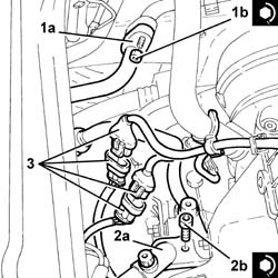
Connect the joint of the coolant return pipe to the engine coolant reservoir.
Connect the rapid attachment for the front fuel supply pipe, fuel manifold pipe side.
Remove the engine oil filler cap.
Place the ignition coils cover back in its housing and secure it using the bolts.
Place the engine oil filler plug back in its housing.
1. Place the power unit reaction rod (1a) back in its housing and fix it tightening the bolts (1b) and (1c) to the recommended torque.
| Fastening | Component | Ø | Value (daNm) | |
|---|---|---|---|---|
| 1b | Bolt | REACTION ROD | M10 | (Bracket on engine/bracket on bodyshell side) 4.5 ÷ 5.5 |
| Fastening | Component | Ø | Value (daNm) | |
|---|---|---|---|---|
| 1c | Bolt | REACTION ROD | M10 | (Bracket on engine/bracket on bodyshell side) 4.5 ÷ 5.5 |
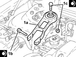
Refit in its seating the fuel vapour recovery pipe and connect the rapid attachment couplings.
Connect the engine front coupling.
Connect the electrical connection to the fuel injection-ignition control unit.
Connect the single-acting valve for the brake servo, brake servo side.
Refit the gear selection and engagement cables to the mounting bracket and secure them with the stop plates.
Connect the gear selector and engagement cables.
1. Fit the spring clip as shown in the figure, i.e. not fully inserted.
Make sure that the hydraulic actuator housing, O-ring and connector on the pipe are absolutely clean and undamaged. If necessary lubricate the O-ring with brake fluid to make it easier to insert it in the pipe. Do not use detergents or mineral lubricants incompatible with the brake fluid materials.
2. Fully fit the hose from the vibration damper to the hydraulic clutch actuator in the hydraulic clutch actuator.
Fully insert the spring clip to lock the pipe.
Refit the rubber protection in its seating.
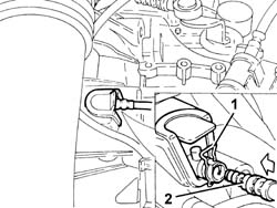
Place back in its housing the air filter assembly and air intake duct complete with air flow meter and connect it to the resonator unit.
Connect the air intake duct to the throttle body.
Connect the oil vapour recirculation pipe to the air intake duct.
Connect the electrical connection to the air flow meter and secure the electrical wiring with the band to the air intake duct.
Connect the electrical connection to the reversing light switch.
Connect the earth cable to the gearbox side rigid power unit mounting.
Proceed with the refitting - 5530B52 Battery DRIP TRAY/SUPPORT - R.R..
Proceed with the refitting - 5530B10 battery - r+r.
Make sure also to connect the starter motor supply lead to the maxi fuse box.
Refill the air conditioner refrigerant system - 5040A10 Air conditioning refrigerant CIRCUIT - Draining and Refilling.
Refill the cooling system - 0010T20 coolant change.
Bleed the air and top up the level of the hydraulic clutch release system - 1820B08 Clutch release HYDRAULIC SYSTEM - Bleeding air and restoring level.
Fill the power steering circuit with the recommended fluid.
| Type | Component | Name | Qty. | |
|---|---|---|---|---|
| Oli [l] | POWER ASSISTED STEERING CIRCUIT | TUTELA GI/A | 1.2 |
Bleed the power steerign system as described below.
With the front wheels raised off the ground, with the engine switched off, carry out 4-5 complete steering wheel rotation cycles (left and right).
Check and, if necessary, top up the fluid level in the reservoir.
Remove the car from the ramp.
Start the engine and carry out 4 - 5 full steering wheel turn cycles (right and left).
Top up the fluid level in the reservoir.
Removing
Position the vehicle on the ramp.
Proceed with the removal - 5530B10 battery - r+r.
When removing the battery, make sure also to disconnect the starter motor supply lead, shown in the figure, from the maxi fuse box.
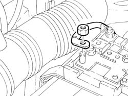
Proceed with the removal - 5530B52 Battery DRIP TRAY/SUPPORT - R.R..
1. Disconnect the earth cable from the gearbox side rigid power unit mounting.
| Name | Connector | |
|---|---|---|
| 1 | Earth on engine | C40A |
2. Disconnect the electrical connection from the reversing light switch.
| Name | Connector | |
|---|---|---|
| 2 | Reversing lights switch | I20 |
1. Disconnect the electrical connection from the air flow meter.
| Name | Connector | |
|---|---|---|
| 1 | Air flow meter | K41 |
Release the air flow meter wiring from the attachment on the air intake duct.
2. Disconnect the oil vapour recirculation pipe from the air intake duct.
3. Disconnect the air intake duct from the throttle body.
1. Remove the air filter assembly and intake duct complete with air flow meter after releasing it from the resonator unit.
1. Move as much as necessary the rubber protection covering the clutch hydraulic actuator pipe joint.
2. Fully withdraw the spring clip securing the pipe to the actuator body.
3. Disconnect the flexible pipe from the vibration damper to the clutch hydraulic actuator, hydraulic actuator side, and secure it.
Recover the clutch fluid which comes out into a suitable container, then plug the pipe and position it to one side.
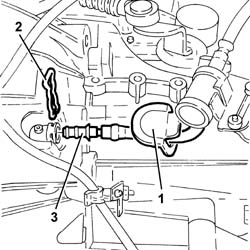
1. Disconnect the gear selector and engagement cables.
To disconnect the gear selection cable, press on the release tabs shown in the figure and move the cable backwards.
2. Remove the stop plates (2a) and release the gear selection and engagement cables from the mounting bracket (2b).
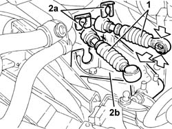
1. Disconnect the single-acting valve for the brake servo, brake servo side.
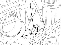
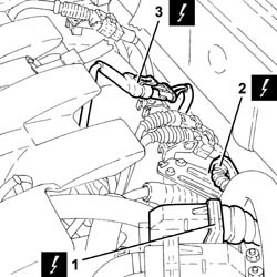
1. Disconnect the electrical connection from the fuel injection-ignition control unit.
| Name | Connector | |
|---|---|---|
| 1 | Engine management ECU | M10A |
2. Disconnect the engine front connection.
| Name | Connector | |
|---|---|---|
| 2 | Front / engine coupling | D4 |
3. Disconnect the electrical connection for the Lambda sensor.
| Name | Connector | |
|---|---|---|
| 3 | Lambda sensor downstream of post-catalyzer | K17 |
1. Disconnect the rapid attachment couplings and remove the fuel vapour recovery pipe.
Plug the fuel vapour recovery system pipes.
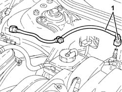
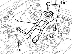
1. Undo the bolts (1a) and (1b) and remove the power unit reaction rod (1c).
Drain the power steering fluid from the reservoir using a suitable syringe.
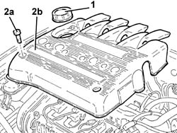
1. Undo and remove the engine oil filler cap.
2. Undo the bolts (2a) and remove the ignition coils cover (2b).
Place the engine oil filler plug back in its housing.
Discharge the fuel supply pressure with the tool connected to the specific valve located on the side of the fuel manifold pipe.
| Name | Country | |
|---|---|---|
| Rapid connector | 1.870.684.000 |
1. Disconnect the rapid attachment of the fuel supply front pipe, fuel manifold pipe side.
Plug the fuel supply front pipe and move it over to one side.
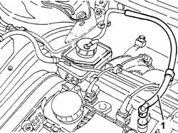
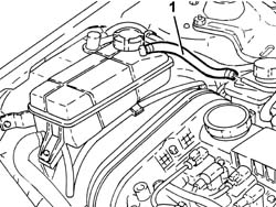
1. Disconnect the coolant return pipe to the coolant reservoir.
Plug the disconnected pipes to prevent impurities from entering the system.
Drain the air conditioner refrigerant system - 5040A10 Air conditioning refrigerant CIRCUIT - Draining and Refilling.
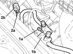
1. Undo the bolt (1a) and disconnect the flange (1b) of the refrigerant inlet/supply pipes from the air conditioner compressor.
2. Undo the nut (2a) and disconnect the flange (2b) of the pipe from the air conditioner condenser to the intermediate connection, intermediate connection side.
Seal the disconnected connectors, using suitable plugs, to prevent humidity and impurities from entering the system.
Proceed with the removal - 4450B12 front or rear wheels (two) - r+r.
Proceed with the removal - 7055B64 Engine compartment DUST shield in front wheel arch (one), left or right - R.R. (Right and left sides).
Proceed with the removal - 7055B42 Additional FRONT WHEEL ARCH (one), left or right - R.R. (Right and left sides).
1. Disconnect the lower coolant outlet hose from the radiator and drain the engine coolant.
Manually press the springs and remove the hose's rapid attachment.
Recover the coolant using a suitable container.
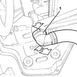
1. Disconnect the upper coolant inlet hose to the radiator.
Manually press the springs and remove the hose's rapid attachment.
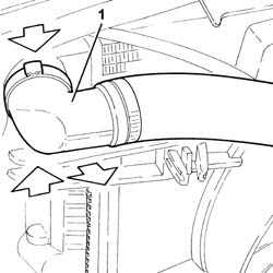
1. Release the wiring from the attachment on the engine coolant supply pipe.
2. Disconnect the engine coolant supply pipe, water pump rigid inlet pipe side.
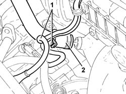
1. Disconnect the coolant return pipe to the climate control heater, thermostat side.
2. Disconnect the coolant return pipe from the climate control heater, water pump rigid inlet pipe side.
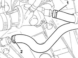
Proceed with the removal - 7210E10 R.R. FRONT BUMPER.
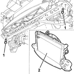
1. Undo the bolts securing the radiator bottom crossmember to the bodywork.
2. Remove the engine cooling radiator complete with fan, air conditioning condenser with pipes and bottom crossmember.
Make sure to release the fan's top pin from the relevant mounting bracket.
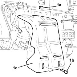
1. Undo the nuts (1a) and bolts (1b), then remove the exhaust manifold heat shield (1c).
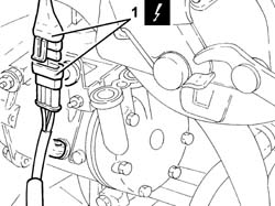
1. Disconnect the electrical connection for the right Lambda sensor and release the wiring from the bands.
| Name | Connector | |
|---|---|---|
| 1 | Lambda sensor on left pre-catalyzer | K16 |
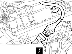
1. Disconnect the electrical connection for the left Lambda sensor and release the wiring from the bands.
| Name | Connector | |
|---|---|---|
| 1 | Lambda sensor on pre-catalyzer | K15 |
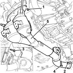
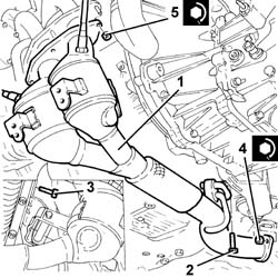
1. Undo the nuts securing the catalytic preconverter to the exhaust manifold.
2. Unscrew the nuts securing the catalytic preconverter to the catalytic converter
3. Undo the bolts securing the catalytic preconverter bracket to the crankcase.
4. Undo the bolt securing the catalytic converter flexible mounting to the front suspension crossmember.
5. Remove the catalytic preconverter complete with Lambda sensors.
Remove the gaskets.
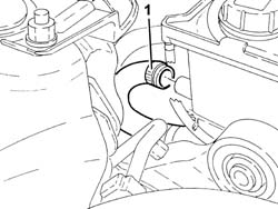
1. Disconnect the return pipe from the heat exchanger to the power steering fluid reservoir, reservoir side.
1. Undo the connector (1a) and disconnect the supply pipe from the power steering pump to the power steering box (1b), pump side.
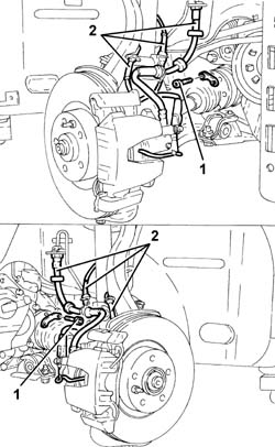
1. Unscrew the bolts securing the drive shafts to the internal differential/drive shaft
2. Release the front brake hoses, brake pad sensor wiring and ABS inductive sensor wiring from their attachments.
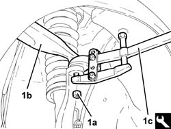
1. Undo the nuts (1a) and disconnect the front upper wishbones (1b) from the vertical links with the tool (1c).
| Name | Country | |
|---|---|---|
| 1c | Extractor | 1.821.169.000 |
Move the drive shafts away from the differential internal drive shaft/intermediate drive shaft.
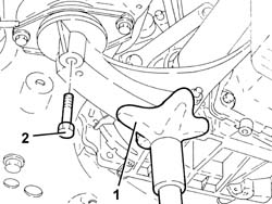
1. Position a hydraulic jack under the power unit rear rigid mounting.
2. Undo the bolt securing the power unit rear rigid mounting to the flexible mounting.
Lower the hydraulic jack slowly and remove.
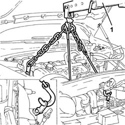
1. Using a hydraulic hoist fitted with suitable chains positioned as shown in the figure, support the power unit.
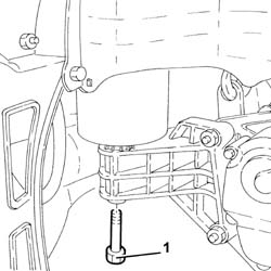
1. Undo the bolts fixing the power unit gearbox side rigid support to the flexible mounting.
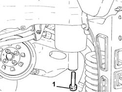
1. Undo the bolt securing the timing side rigid engine support to the flexible mounting.
Slowly lower the power unit with the hydraulic hoist until it is resting on the ground.
Release the hydraulic hoist's chains from the power unit.
Raise the car on a lift.
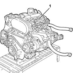
1. Using the hydrualic hoist fitted with suitable chains as described above, position the power unit on a platform.
Refitting
Using a hydraulic hoist fitted with suitable chains as described above, position the power unit under the car.
Release the hydraulic hoist's chains from the power unit.
Lower the car with the lift.
Through the engine compartment, support the power unit with the hydraulic hoist fitted with suitable chains.
Slowly lift the power unit with the hydraulic hoist until it is resting in its seating in the engine compartment.
1. Tighten the bolt fixing the timing side rigid engine support to the flexible mounting to the recommended torque.
| Fastening | Component | Ø | Value (daNm) | |
|---|---|---|---|---|
| 1 | Bolt | ENGINE MOUNT TIMING SIDE | M12 | (Flexible mounting side) 7.9 ÷ 9.7 |
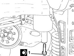
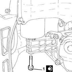
1. Tighten to the specified torque the bolt fixing the power unit gearbox side rigid support to the flexible mounting.
| Fastening | Component | Ø | Value (daNm) | |
|---|---|---|---|---|
| 1 | Bolt | POWER UNIT GEAR BOX END RIGID MOUNT | M10 | (Flexible mounting side) 4.2 ÷ 5.1 |
Release the hydraulic hoist's chains from the power unit.
1. Position a hydraulic jack under the power unit rear rigid mounting and raise it slowly until it is in contact with the relevant flexible mounting.
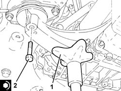
2. Tighten the bolt fixing the power unit rigid rear support to the flexible mounting to the recommended torque.
| Fastening | Component | Ø | Value (daNm) | |
|---|---|---|---|---|
| 2 | Bolt | POWER UNIT RIGID REAR MOUNT | M12 | (Flexible mounting side) 7.5 ÷ 9.2 |
Remove the hydraulic jack.
Refit the drive shafts in their seating in contact with the internal differential drive shaft/intermediate drive shaft.
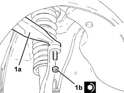
1. Connect the front upper track control arms (1a) to the steering knuckles and tighten the nuts (1b) to the specified torque.
| Fastening | Component | Ø | Value (daNm) | |
|---|---|---|---|---|
| 1b | Nut | FRONT SUSPENSION TOP LEVER | M10 | (Steering knuckle side) 4.3 ÷ 4.7 |
1. Tighten the bolts securing the drive shafts to the differential internal drive shaft/intermediate drive shaft to the specified torque.
| Fastening | Component | Ø | Value (daNm) | |
|---|---|---|---|---|
| 1 | Bolt | DRIVESHAFT | M8 | (Differential. internal. driveshaft./side..) 3.5 ÷ 4.3 |
2. Secure the front brake hoses, brake pad wear wiring and BAS inductive sensor wiring.
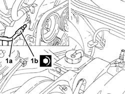
1. Connect the supply pipe from power steering pump to power steering box (1a), pump side, and tighten the connector (1b) to the specified torque.
| Fastening | Component | Ø | Value (daNm) | |
|---|---|---|---|---|
| 1b | Connector | PIPE BTWN PUMP + POWER STEERING BOX | M16 | (Power assisted steering pump side) 4.5 ÷ 5.5 |
Connect the return pipe from the heat exchanger to the power steering fluid reservoir, reservoir side.
1. Place the catalytic preconverter complete with Lambda sensors and gaskets back in its housing.
2. Tighten the bolt securing the catalytic preconverter flexible mounting to the front suspension crossmember.
3. Tighten the bolts securing the catalytic preconverter mounting bracket to the crankcase.
4. Tighten the nuts fixing the catalytic preconverter to the catalytic converter to the specified torque.
| Fastening | Component | Ø | Value (daNm) | |
|---|---|---|---|---|
| 4 | Nut | CATALYTIC PRE-CONVERTER | M8 | (Catalytic converter side) 2.7 ÷ 3.3 |
5. Tighten, to the specified torque, the nuts securing the catalytic preconverter to the exhaust manifold.
| Fastening | Component | Ø | Value (daNm) | |
|---|---|---|---|---|
| 5 | Nut | CATALYTIC PRE-CONVERTER | M8 | (Manifold side) 2.7 ÷ 3.3 |
Connect the right and left Lambda probe electrical connection, then secure the wiring.
Refit the exhaust manifold heat shield in its seating and secure it with its nuts and bolts.
Place back in its housing the engine cooling radiator, complete with fan, air conditioning condenser with pipes and bottom crossmember.
Check that the fan's top pin is fitted correctly in its mounting bracket.
Tighten the bolts securing the radiator bottom crossmember to the bodywork.
Proceed with the refitting - 7210E10 R.R. FRONT BUMPER.
Connect the coolant return hose from the climate control heater on the side of the rigid inlet pipe to the water pump.
Connect the coolant supply pipe to the climate control heater, thermostat side.
Connect the engine coolant supply pipe, water pump rigid inlet pipe side.
Connect the upper coolant inlet hose to the radiator.
Connect the lower coolant outlet hose from the radiator.
Proceed with the removal - 7055B42 Additional FRONT WHEEL ARCH (one), left or right - R.R. (Right and left sides).
Proceed with the removal - 7055B64 Engine compartment DUST shield in front wheel arch (one), left or right - R.R. (Right and left sides).
Proceed with the refitting - 4450B12 front or rear wheels (two) - r+r.
1. Connect the flange of the pipe from the air conditioner condenser to the intermediate connector (1a), intermrediate connector side, and tighten the nut (1b) to the specified torque.
Replace the O-Ring seals for the connectors. Only use green coloured seals, resistant to R134A coolant fluid. Lubricate the threads of the connectors using anti-freeze.
| Fastening | Component | Ø | Value (daNm) | |
|---|---|---|---|---|
| 1b | Nut | COOLANT SYSTEM FITTINGS | M6 | 0.7 ÷ 1.1 |
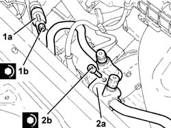
2. Connect the flange (2a) of the refrigerant inlet/supply pipes to the air conditioner compressor and tighten the bolt (2b) to the specified torque.
| Fastening | Component | Ø | Value (daNm) | |
|---|---|---|---|---|
| 2b | Bolt | COMPRESSOR PIPE CONNECTORS | M10 | (Air conditioning compressor side) 2.8 ÷ 4.2 |
Connect the joint of the coolant return pipe to the engine coolant reservoir.
Connect the rapid attachment for the front fuel supply pipe, fuel manifold pipe side.
Remove the engine oil filler cap.
Place the ignition coils cover back in its housing and secure it using the bolts.
Place the engine oil filler plug back in its housing.
1. Place the power unit reaction rod (1a) back in its housing and fix it tightening the bolts (1b) and (1c) to the recommended torque.
| Fastening | Component | Ø | Value (daNm) | |
|---|---|---|---|---|
| 1b | Bolt | REACTION ROD | M10 | (Bracket on engine/bracket on bodyshell side) 4.5 ÷ 5.5 |
| Fastening | Component | Ø | Value (daNm) | |
|---|---|---|---|---|
| 1c | Bolt | REACTION ROD | M10 | (Bracket on engine/bracket on bodyshell side) 4.5 ÷ 5.5 |
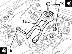
Refit in its seating the fuel vapour recovery pipe and connect the rapid attachment couplings.
Connect the electrical connection for the Lambda sensor.
Connect the engine front coupling.
Connect the electrical connection to the fuel injection-ignition control unit.
Connect the single-acting valve for the brake servo, brake servo side.
Refit the gear selection and engagement cables to the mounting bracket and secure them with the stop plates.
Connect the gear selector and engagement cables.
1. Fit the spring clip as shown in the figure, i.e. not fully inserted.
Make sure that the hydraulic actuator housing, O-ring and connector on the pipe are absolutely clean and undamaged. If necessary lubricate the O-ring with brake fluid to make it easier to insert it in the pipe. Do not use detergents or mineral lubricants incompatible with the brake fluid materials.
2. Fully fit the hose from the vibration damper to the hydraulic clutch actuator in the hydraulic clutch actuator.
Fully insert the spring clip to lock the pipe.
Refit the rubber protection in its seating.
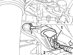
Place the air filter assembly and air intake duct complete with air flow meter back in its housing and connect it to the resonator unit.
Connect the air intake duct to the throttle body.
Connect the oil vapour recirculation pipe to the air intake duct.
Connect the electrical connection to the air flow meter and secure the electrical wiring with the band to the air intake duct.
Connect the electrical connection to the reversing light switch.
Connect the earth cable to the gearbox side rigid power unit mounting.
Proceed with the refitting - 5530B52 Battery DRIP TRAY/SUPPORT - R.R..
Proceed with the refitting - 5530B10 battery - r+r.
Make sure also to connect the starter motor supply lead to the maxi fuse box.
Refill the air conditioner refrigerant system - 5040A10 Air conditioning refrigerant CIRCUIT - Draining and Refilling.
Refill the cooling system - 0010T20 coolant change.
Bleed the air and top up the level of the hydraulic clutch release system - 1820B08 Clutch release HYDRAULIC SYSTEM - Bleeding air and restoring level.
Fill the power steering circuit with the recommended fluid.
| Type | Component | Name | Qty. | |
|---|---|---|---|---|
| Oli [l] | POWER ASSISTED STEERING CIRCUIT | TUTELA GI/A | 1.2 |
Bleed the power steering system as described below
With the front wheels raised off the ground, with the engine switched off, carry out 4-5 complete steering wheel rotation cycles (left and right).
Check and, if necessary, top up the fluid level in the reservoir.
Remove the car from the ramp.
Start the engine and carry out 4 - 5 full steering wheel turn cycles (right and left).
Top up the fluid level in the reservoir.
Removing
Proceed with the removal - 5530B10 battery - r+r.
Proceed with the removal - 5530B52 Battery DRIP TRAY/SUPPORT - R.R..
Drain the air conditioner refrigerant system - 5040A10 Air conditioning refrigerant CIRCUIT - Draining and Refilling.
Proceed with the removal - 4450B12 front or rear wheels (two) - r+r.
Proceed with the removal - 7055B54 under-engine guard - r r.
Proceed with the removal - 7055B64 Engine compartment DUST shield in front wheel arch (one), left or right - R.R. (Right and left sides).
Proceed with the removal - 7055B42 Additional FRONT WHEEL ARCH (one), left or right - R.R. (Right and left sides).
Proceed with the removal - 7210E10 R.R. FRONT BUMPER.
Proceed with the removal - 1004B24 power unit with manual gearbox with hydraulic selection - r r.
Refitting
Proceed with the refitting - 1004B24 power unit with manual gearbox with hydraulic selection - r r.
Proceed with the refitting - 7210E10 R.R. FRONT BUMPER.
Proceed with the removal - 7055B42 Additional FRONT WHEEL ARCH (one), left or right - R.R. (Right and left sides).
Proceed with the removal - 7055B64 Engine compartment DUST shield in front wheel arch (one), left or right - R.R. (Right and left sides).
Proceed with the refitting - 7055B54 under-engine guard - r r.
Proceed with the refitting - 4450B12 front or rear wheels (two) - r+r.
Check the level of the fluid in the electro-hydraulic selection gearbox and if necessary top it up - 2127C04 ELECTROHYDRAULIC selection gearbox hydraulic system FLUID - Check level and top up if necessary..
Bleed the air from the electro-hydraulic selection gearbox hydraulic system - 2127C06 Electro-hydraulic selection manual gearbox HYDRAULIC SYSTEM - Bleeding air.
Proceed with the refitting - 5530B52 Battery DRIP TRAY/SUPPORT - R.R..
Proceed with the refitting - 5530B10 battery - r+r.
Refill the air conditioner refrigerant system - 5040A10 Air conditioning refrigerant CIRCUIT - Draining and Refilling.
Refill the cooling system - 0010T20 coolant change.
Removing
Position the vehicle on the ramp.
Drain the air conditioner coolant circuit - 5040A10 Air conditioning refrigerant CIRCUIT - Draining and Refilling.
Proceed with removal - 1048A48 throttle heater sleeve - r r.
Proceed with removal - 5530B10 battery - r+r.
Proceed with removal - 5530B52 Battery DRIP TRAY/SUPPORT - R.R..
Proceed with removal - 1048A10 air cleaner filtering element - replace.
Proceed with removal - 4450B12 front or rear wheels (two) - r+r.
Proceed with removal - 7055B54 under-engine guard - r r.
Proceed with removal - 7055B64 Engine compartment DUST shield in front wheel arch (one), left or right - R.R..
Proceed with removal - 7055B42 Additional FRONT WHEEL ARCH (one), left or right - R.R..
Proceed with removal - 7210E10 R.R. FRONT BUMPER.
Proceed with the removal - 5540B76 Front LIGHT CLUSTER with fog light (one), left or right - R.R. with interfering components removed (Right and left sides).
Proceed with removal - 7025A34 bonnet lid lock (one) - r+r or repair.
Proceed with removal - 7210A15 R.R. HEADLAMP HOUSING/FRONT WING CROSSMEMBER.
Proceed with removal - 1088B20 engine cooling radiator - r + r.
1. Loosen the band and disconnect the upper coolant inlet hose to the radiator thermostat side and remove it.
2. Loosen the band and disconnect the lower radiator coolant outlet hose from the radiator, thermostat side.
3. Loosen the band and disconnect the intermediate coupling for the engine cooling system supply pipe.
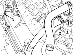
1. Undo the bolts (1a) and remove the lower radiator crossmember (1b) complete with engine cooling system pipes (1c).
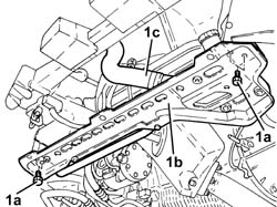
1. Undo the nut (1a) and disconnect the earth lead (1b) from the gearbox side rigid power unit support.
| Name | Connector | |
|---|---|---|
| 1b | Battery earth | C1 |
2. Loosen the bands and disconnect the radiator power assisted steering fluid supply and return pipes, rigid pipes side.
Collect the power assisted steering fluid in a suitable container.
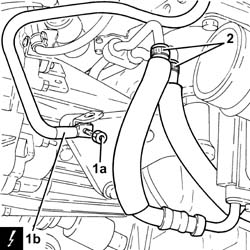
1. Undo the nuts (1a) and remove the power assisted steering fluid system cooling radiator mounting bracket (1b) complete with radiator (1c), duct (1d) and pipes (1e).
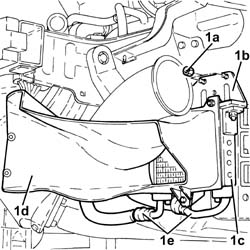
1. Undo the bolt (1a) and remove the cold air intake for the air filter (1b)
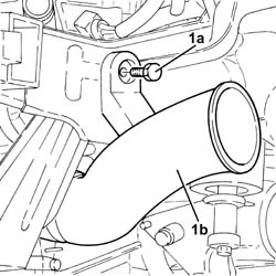
1. Undo the connector (1a) and disconnect the delivery pipe from pump to power steering box (1b), steering box side.
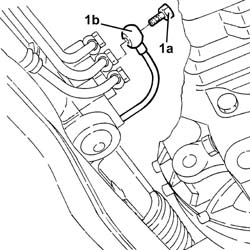
1. Loosen the band and disconnect the intermediate coupling for the return pipe from the power assisted steering box to the radiator.
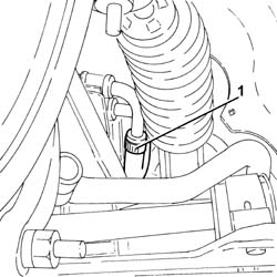
Proceed with removal - 1076B82 left exhasust pipe between catalytic preconverter and converter r r.
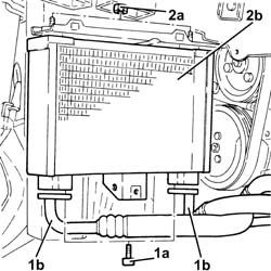
1. Undo the bolts (1a) and disconnect the engine oil inlet and outlet pipes (1b), engine oil cooling radiator side.
Collect the engine oil in a suitable container.
2. Undo the nuts (2a) and remove the engine oil cooling radiator (2b).
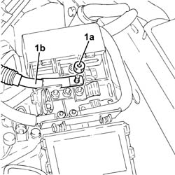
1. Undo the nut (1a) and disconnect the starter motor electrical connection (1b) from the maxi-fuse box.
1. Disconnect the electrical connection from the reversing lights switch.
| Name | Connector | |
|---|---|---|
| 1 | Reversing lights switch | I20 |
2. Disconnect the gear selector and engagement cables.
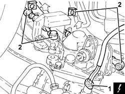
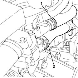
1. Loosen the band and disconnect the coolant return pipe to the climate control heater, connector side.
2. Loosen the band and disconnect the coolant return pipe from the climate control heater, thermostat side.
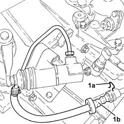
Remove the protective cap on the master cylinder bleed valve.
Connect the collection system (pipe and reservoir) to the bleed valve on the master cylinder.
Operate the clutch pedal until the brake-clutch fluid reservoir is empty.
1. Remove the split pin (1a) and disconnect the pipe between the vibration damper and the clutch operating cylinder (1b), vibration damper side.
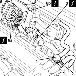
1. Disconnect the rapid connector for the fuel vapour recirculation pipe from the air chamber.
2. Loosen the band and disconnect the servo brake vacuum intake pipe from the air chamber.
3. Disconnect the electrical connection from the fuel injection/ignition control unit.
| Name | Connector | |
|---|---|---|
| 3 | Engine management ECU | M10 |
4. Open the electrical connections box cover.
5. Disconnect the engine coupling.
6. Disconnect the electrical connections (6a) and (6b) for the rear Lambda sensors and the catalytic converter.
| Name | Connector | |
|---|---|---|
| 6a | Lambda sensor downstream of post-catalyzer | K17 |
| Name | Connector | |
|---|---|---|
| 6b | Lambda sensor on catalyzer -2 | K18 |
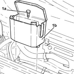
1. Undo the bolts (1a) and remove the electrical connections box (1b).
1. Loosen the band and disconnect the coolant return pipe from the engine coolant reservoir.
2. Undo the bolts (2a) and remove the power unit reaction rod (2b).
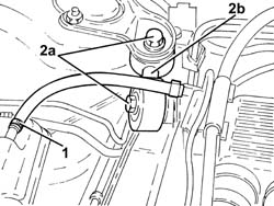
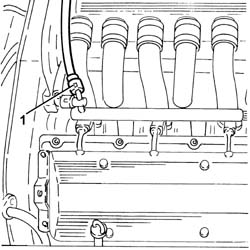
Discharge the fuel supply pressure.
1. Disconnect the rapid attachment for the fuel supply pipe.
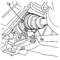
1. Undo the bolts (1a) and disconnect the right driveshaft (1b) from the intermediate shaft.
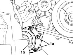
1. Undo the bolts (1a) and disconnect the left driveshaft (1b) from the differential inner shaft.
Proceed with removal - 1008A44 rear rigid mount - r r.
Position a suitable support under the power unit.
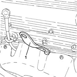
1. Fit a suitable bracket for supporting the power unit on the left cylinder head.
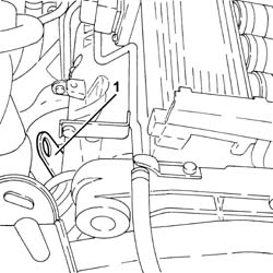
1. Fit a suitable bracket for supporting the power unit on the right cylinder head.
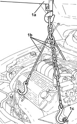
1. Support the power unit using a hydraulic hoist (1a), fitted with suitable chains (1b) connected to the brackets fitted previously and to the bracket (1c) already on the gearbox.
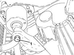
1. Undo the bolts fixing the power unit gearbox side rigid support to the flexible mounting.
1. Undo the nut fixing the timing side rigid engine support to the flexible mounting.
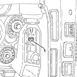
Move the power unit forwards to prevent interference with the front suspension crossmember, then slowly lower the power unit with the hydraulic hoist until it is resting on the support positioned previously.
Refitting
Place the power unit back in the engine compartment using the hydraulic hoist.
1. Tighten the nut fixing the timing side rigid engine support to the flexible mounting.
| Fastening | Component | Ø | Value (daNm) | |
|---|---|---|---|---|
| 1 | Nut | ENGINE MOUNT TIMING SIDE | M10 | (Flexible mounting side) 4.5 ÷ 5.5 |
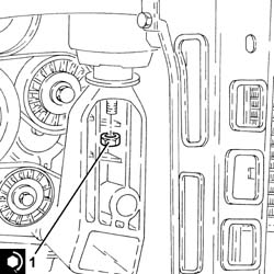
1. Tighten the bolt fixing the power unit gearbox side rigid support to the flexible mounting.
| Fastening | Component | Ø | Value (daNm) | |
|---|---|---|---|---|
| 1 |
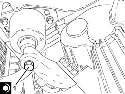
Remove the hydraulic hoist fitted with suitable chains for supporting the power unit.
Remove the brackets fitted for supporting the power unit.
Remove the support positioned previously under the power unit.
Proceed with refitting - 1008A44 rear rigid mount - r r.
1. Connect the left driveshaft (1a) to the differential inner shaft and fix it tightening the bolts (1b) to the recommended torque.
| Fastening | Component | Ø | Value (daNm) | |
|---|---|---|---|---|
| 1b |
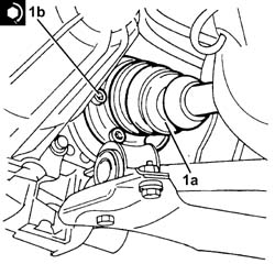
1. Connect the right driveshaft (1a) to the intermediate driveshaft and tighten the bolts (1b) to the specified torque.
| Fastening | Component | Ø | Value (daNm) | |
|---|---|---|---|---|
| 1b |
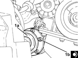
Connect the rapid attachment for the fuel supply pipe.
1. Place the power unit reaction rod (1a) back in its housing and fix it tightening the bolts (1b) to the recommended torque.
| Fastening | Component | Ø | Value (daNm) | |
|---|---|---|---|---|
| 1b | Bolt | REACTION ROD | M10 | 4.5 ÷ 5.5 |
2. Connect the coolant return pipe to the engine coolant reservoir and tighten the band.
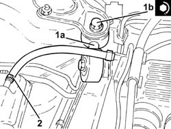
Place the electrical connections box back in its housing and secure it using the bolts.
Connect the electrical connections for the rear Lambda sensors to the catalytic converter.
Connect the engine junction.
Close the electrical connections box cover.
Connect the electrical connection to the fuel injection/ignition control unit.
Connect the brake servo vacuum intake pipe to the air chamber and tighten the band.
Connect the rapid connector for the fuel vapour recirculation pipe to the air chamber.
Connect the pipe from the vibration damper to the clutch operating cylinder, vibration damper side and secure it using the split pin.
Connect the engine coolant return pipe from the climate control system heater, thermostat side, and tighten the band.
Connect the engine coolant return pipe from the climate control system heater, connector side, and tighten the band.
Connect the gear selector and engagement cables.
Connect the electrical connection to the reversing lights switch.
Connect the starter motor supply connector to the maxi-fuse box and tighten the nut.
Place the engine oil cooling radiator back in its housing and fix it using the nuts.
Connect the engine oil inlet and outlet pipes, engine cooling radiator side and tighten the bolts.
Proceed with refitting - 1076B82 left exhasust pipe between catalytic preconverter and converter r r.
Connect the intermediate coupling for the return pipe from the power assisted steering box to the radiator and tighten the band.
1. Connect the supply pipe from pump to power steering box (1a), power steering box side, and tighten the connector (1b) to the specified torque.
| Fastening | Component | Ø | Value (daNm) | |
|---|---|---|---|---|
| 1b | Connector | PIPE BTWN PUMP + POWER STEERING BOX | M14 | (Power assisted steering box side) 3.6 ÷ 4.4 |
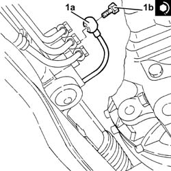
Place the cold air intake back in its housing and secure it using the appropriate bolts.
Place the power assisted steering system fluid cooling radiator mounting bracket back in its housing complete with radiator, duct and pipes and fasten it using the nuts.
Connect the power assisted steering fluid supply and return pipes to the radiator, rigid pipes side and tighten the bands.
Connect the earth lead to the gearbox side rigid power unit support and secure it using the nut.
Place the lower radiator crossmember back in its housing complete with engine cooling system pipes and fasten it using the bolts.
Connect the intermediate coupling for the engine cooling system supply pipe and tighten the band.
Connect the lower coolant outlet hose from the radiator, thermostat side, and tighten the band.
Place the radiator coolant upper hose in its housing, connect it to the thermostat and tighten the band.
Proceed with refitting - 1088B20 engine cooling radiator - r + r.
Proceed with refitting - 7210A15 R.R. HEADLAMP HOUSING/FRONT WING CROSSMEMBER.
Proceed with refitting - 7025A34 bonnet lid lock (one) - r+r or repair.
Proceed with the refitting - 5540B76 Front LIGHT CLUSTER with fog light (one), left or right - R.R. with interfering components removed (Right and left sides).
Proceed with refitting - 7210E10 R.R. FRONT BUMPER.
Proceed with refitting - 7055B42 Additional FRONT WHEEL ARCH (one), left or right - R.R..
Proceed with refitting - 7055B64 Engine compartment DUST shield in front wheel arch (one), left or right - R.R..
Proceed with refitting - 4450B12 front or rear wheels (two) - r+r.
Proceed with refitting - 1048A10 air cleaner filtering element - replace.
Proceed with refitting - 5530B52 Battery DRIP TRAY/SUPPORT - R.R..
Proceed with refitting - 5530B10 battery - r+r.
Proceed with refitting - 1048A48 throttle heater sleeve - r r.
Refill the engine oil lubrication system - 0010T11 engine oil check level and top up.
Refill the engine cooling system with coolant - 0010T20 coolant change.
Bleed the air and top up the level in the hydraulic clutch system - 0010T67 hydraulic clutch system bleed air.
Fill the air conditioner coolant circuit - 5040A10 Air conditioning refrigerant CIRCUIT - Draining and Refilling.
Fill the power steering circuit with the recommended fluid.
| Type | Component | Name | Qty. | |
|---|---|---|---|---|
| Fluid [l] | HYDRAULIC POWER ASSISTED STEERING SYSTEM | TUTELA GI/A | 1.2 |
The table shows the total quantity of fluid present in the power assisted steering circuit.
Bleed the power steering system as described below
With the front wheels raised off the ground, with the engine switched off turn the steering wheel to full lock, left and right, 4-5 times.
Check and, if necessary, top up the fluid level in the reservoir.
Remove the car from the ramps.
Start the engine and carry out 4 - 5 full steering wheel turn cycles (right and left).
Top up the fluid level in the reservoir.
Proceed with refitting - 7055B54 under-engine guard - r r.
Removing
Place the car on a ramp.
- 5040A10 Air conditioning refrigerant CIRCUIT - Draining and Refilling
- 4450B12 front or rear wheels (two) - r+r
- 7055B54 under-engine guard - r r
- 7055B64 Engine compartment DUST shield in front wheel arch (one), left or right - R.R.
- 7055B42 Additional FRONT WHEEL ARCH (one), left or right - R.R.
- 1016A10 sound-proofing cover - r + r
- 5530B52 Battery DRIP TRAY/SUPPORT - R.R.
1. Open the band and disconnect the air pipe from the throttle casing.
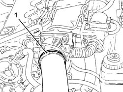
Position a suitable container under the engine to collect the coolant.
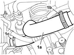
1. Disconnect the lower pipe (1a) for the radiator from the rigid pipe (1b) and from the radiator (1c), the remove it.
To disconnect the pipe from the radiator, press the spring manually and release the rapid attachment for the pipe from the connector on the radiator.
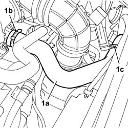
1. Disconnect the upper pipe (1a) for the radiator from the thermostat (1b) and from the radiator (1c), then remove it.
To disconnect the pipe from the radiator, press the spring manually and release the rapid attachment for the pipe from the connector on the radiator.
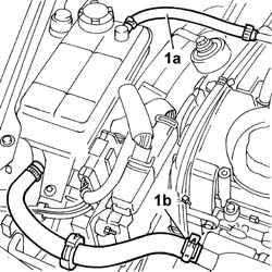
1. Disconnect the recirculation pipe (1a) and the water supply pipe (1b) to the water pump rigid supply pipe from the coolant reservoir.
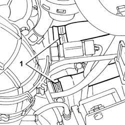
1. Disconnect the two heater supply and return pipes from the thermostat.
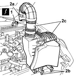
1. Disconnect the electrical connection from the air flow meter.
| Name | Connector | |
|---|---|---|
| 1 | Air flow meter | K41 |
2. Disconnect the band (2a), release it from the lower fixing pins (2b), release the filter casing from the cold air intake pipe, then remove the complete air filter casing (2c).
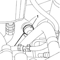
1. Disconnect the single-acting valve for the vacuum pipe from the brake servo.
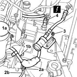
1. Lift up the retaining spring (1a) and release the oil pipe (1b) for the hydraulic clutch release cylinder.
2. Undo the nut (2a) and disconnect the earth lead (2b) from the gearbox.
| Name | Connector | |
|---|---|---|
| 2b | Battery earth | C1 |
3. Undo the nuts fixing the damper to the bracket.
4. Disconnect the electrical connection on the gearbox for the reversing sensor.
| Name | Connector | |
|---|---|---|
| 4 | Reversing lights switch | I20 |
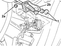
1. Remove the two gear selection and engagement flexible transmission cable ends from the gear lever.
2. Undo the fixing nuts (2a) and move the gear selector and engagement cables (2b), complete with mounting bracket, away from the working area.
1. Undo the fixing nut (1a), lift up the pre-heating control unit and disconnect the electrical connection (1b).
| Name | Connector | |
|---|---|---|
| 1b | Plug preheating control unit | M15 |
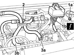
2. Disconnect the supply pipe to the pressure pump from the fuel filter.
3. Disconnec the supply pipe to the fuel filter (3a) and the return pipe to the reservoir (3b) from the return manifold.
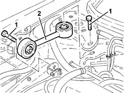
1. Undo the fixing bolts.
2. Remove the reaction link.
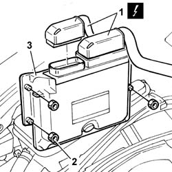
1. Disconnect the electrical connections for the engine management control unit.
| Name | Connector | |
|---|---|---|
| 1 | Engine management ECU | M10 |
2. Undo the retaining nuts.
3. Remove the engine management control unit from its housing.
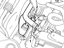
1. Disconnect the supply pipe from the power steering fluid reservoir to the pump.
2. Disconnect the supply pipe from the power assisted steering fluid pump to the box.
1. Withdraw the retaining bolt.
2. Disconnect the two high and low pressure pipes from the compressor.
3. Undo the fixing nut (3a) and separate the two sections (3b) of the low pressure pipe.
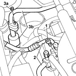
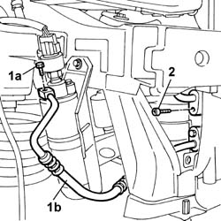
1. Undo the bolt (1a) and disconnect the pipe (1b) connected to the condenser from the drier filter.
2. Undo the fixing bolt and remove the high and low pressure pipe assembly.
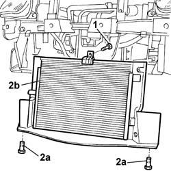
1. Undo the upper bolt fixing the radiator to the upper crossmember.
Raise the lift.
Position a hydraulic lift under the lower crossmember.
2. Undo the fixing bolts (2a) for the lower crossmember, slowly lower the hydraulic lift and remove the radiator-fan-condenser (2b) assembly. -
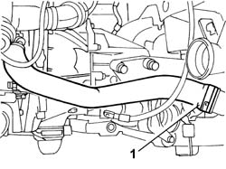
1. Disconnect the air supply pipe to the air/air heat exchanger.
1. Undo the bolts fixing the left and right driveshafts.
2. Release the brake caliper flexible pipes, the electrical wiring for the brake pad wear sensors and the electrical wiring for the ABS sensors from the fastenings.
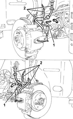
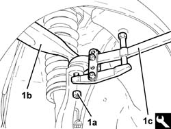
1. Undo the nuts (1a) and disconnect the front upper wishbones (1b) from the vertical links with the tool (1c).
| Name | Country | |
|---|---|---|
| 1c | Extractor | 1.821.169.000 |
Release the left and right driveshafts from the attachments.
- 1076B50 exhaust pipe attachment to engine - r + r
- 1008A44 rear rigid mount - r r
Position a suitable support under the power unit.
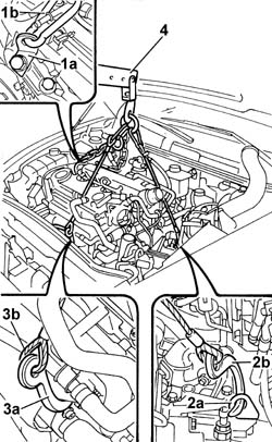
1. Position a bracket (1a), complete with hook (1b), on the engine support for the reaction rod.
2. Fit the bracket (2a) on the bell housing and secure the chain and hook assembly (2b) to it.
3. Use the hook (3a), complete with chain (3b) and secure it to the exhaust manifold.
4. Secure the chains to the hydraulic lifting device and tension the engine.
1. Undo the bolt fixing the timing side engine support.
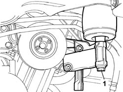
Lift the power unit, tilting the gearbox assembly downwards, rotate the assembly placing the timing side towards the front of the vehicle then, using the hydraulic lift, position the power unit on a suitable support.
Take great care when rotating and removing the engine not to damage the components fitted on the vehicle. Whilst rotating the power unit, check that the gearbox-differential unit does not come into contact with the ABS unit.
Refitting
Support the power unit using a hydraulic hoist fitted with suitable chains and position the power unit in the special housing in the vehicle.
Tighten the bolt fixing the timing side engine support to torque.
| Fastening | Component | Ø | Value (daNm) | |
|---|---|---|---|---|
| Bolt | ENGINE MOUNT TIMING SIDE | M12 | 4.2 - 5.2 |
Remove the chains, the hooks and the brackets fitted for supporting the power unit.
Remove the stand positioned previously under the power unit.
- 1008A44 rear rigid mount - r r
- 1076B50 exhaust pipe attachment to engine - r + r
Fit the left and right driveshafts on the differential and the intermediate driveshaft.
Connect the front upper track control arms to the steering knuckles.
Tighten the nuts fixing the track control arms to the steering knuckle to torque.
| Fastening | Component | Ø | Value (daNm) | |
|---|---|---|---|---|
| Nut | FRONT SUSPENSION TOP LEVER | M10 | (Steering knuckle side) 4.3 ÷ 4.7 |
Tighten the bolts securing the drive shafts to the differential internal drive shaft/intermediate drive shaft to the specified torque.
| Fastening | Component | Ø | Value (daNm) | |
|---|---|---|---|---|
| Bolt | DRIVESHAFT | M8 | (Differential. internal. driveshaft./side..) 3.5 ÷ 4.3 |
Secure the front brake hoses, brake pad wear wiring and BAS inductive sensor wiring.
Connect the air supply pipe to the air/air heat exchanger.
Place back in its housing the engine cooling radiator, complete with fan, air conditioning condenser with pipes and bottom crossmember.
Check that the fan's top pin is fitted correctly in its mounting bracket.
Tighten the bolts securing the radiator bottom crossmember to the bodywork.
Fit the high and low pressure pipes assembly.
Replace the O-Ring seals for the connectors. Only use green coloured seals, resistant to R134A refrigerant. Lubricate the threads of the connectors using anti-freeze.
Tighten the bolt fixing the pipe to the drier filter to torque.
| Fastening | Component | Ø | Value (daNm) | |
|---|---|---|---|---|
| Bolt | COOLANT SYSTEM FITTINGS | M6 | 0.9 |
Connect the low pressure pipes and tighten the securing nut to torque.
Replace the O-Ring seals for the connectors. Only use green coloured seals, resistant to R134A refrigerant. Lubricate the threads of the connectors using anti-freeze.
| Fastening | Component | Ø | Value (daNm) | |
|---|---|---|---|---|
| Nut | COOLANT SYSTEM FITTINGS | M6 | 0.9 |
Connect the pipes to the air conditioning compressor.
| Fastening | Component | Ø | Value (daNm) | |
|---|---|---|---|---|
| Bolt | COMPRESSOR PIPE CONNECTORS | M10 | (Air conditioning compressor side) 2.8 ÷ 4.2 |
Connect the supply pipe from the pump to the power assisted steering box.
Connect the supply pipe from the power steering fluid reservoir to the pump.
Fit the engine management control unit in the housing.
Tighten the nuts fixing the control unit to the support.
Connect the electrical connections for the engine management control unit.
| Name | Connector | |
|---|---|---|
| Engine management ECU | M10 |
Place the power unit reaction rod back in its housing and fix it tightening the bolts to the recommended torque.
| Fastening | Component | Ø | Value (daNm) | |
|---|---|---|---|---|
| Bolt | REACTION ROD | M10 | (Support side) 4.5 ÷ 5.1 |
| Fastening | Component | Ø | Value (daNm) | |
|---|---|---|---|---|
| Bolt | REACTION ROD | M10 | (Support side) 4.5 ÷ 5.1 |
Connect the supply pipe to the fuel filter and the return pipe to the reservoir to the return manifold.
Connect the fuel supply pipe to the pressure pump to the fuel filter.
Position the pre-heating control unit, tighten the nut and connect the electrical connection.
| Name | Connector | |
|---|---|---|
| Plug preheating control unit | M15 |
Position the gear selection and engagement flexible transmission cables, complete with mounting bracket, on the gearbox.
Tighten the nuts fixing the bracket to the gearbox.
Fit the two gear selection and engagement flexible transmission cables on the mounting bracket.
Connect the electrical connection for the reversing sensor to the gearbox.
| Name | Connector | |
|---|---|---|
| Reversing lights switch | I20 |
Tighten the nuts fixing the damper to the mounting bracket on the gearbox.
Connect the earth lead to the gearbox.
| Name | Connector | |
|---|---|---|
| Battery earth | C1 |
Connect the oil pipe for the hydraulic clutch release cylinder.
Check that the spring is fully engaged and that the pipe is correctly positioned.
Connect the vacuum pipe single-acting valve to the brake servo.
Fit the complete air filter casing complete with filter element.
Fasten the lower pins, secure the cold air intake pipe and connect the turbocharger air supply pipe.
Connect the electrical connection for the air flow meter.
| Name | Connector | |
|---|---|---|
| Air flow meter | K41 |
Connect the two heater supply and return pipes to the thermostat.
Connect the recirculation pipe and the water supply pipe to the pump water supply rigid pipe to the reservoir.
Connect the upper radiator pipe to the thermostat and the radiator.
Fit the lower radiator pipe, connecting it to the rigid pipe and the radiator.
Connect the air pipe to the throttle casing.
- 5530B52 Battery DRIP TRAY/SUPPORT - R.R.
- 1016A10 sound-proofing cover - r + r
- 7055B42 Additional FRONT WHEEL ARCH (one), left or right - R.R.
- 7055B64 Engine compartment DUST shield in front wheel arch (one), left or right - R.R.
- 7055B54 under-engine guard - r r
- 4450B12 front or rear wheels (two) - r+r
- 5040A10 Air conditioning refrigerant CIRCUIT - Draining and Refilling
- 0010T21 coolant check density and top up if necessary
- 0010T62 BRAKE and/or CLUTCH FLUID - Replace. fluid - Includes. washing pipes and bleeding air
Removing
Position the vehicle on the ramp.
Proceed with removal - 7025A12 Engine front sound insulation COVER - R.R..
Proceed with removal - 7025A14 Bonnet LID - R.R..
Proceed with removal - 1016A10 sound-proofing cover - r + r.
Drain the air conditioner coolant circuit - 5040A10 Air conditioning refrigerant CIRCUIT - Draining and Refilling.
Proceed with removal - 4450B12 front or rear wheels (two) - r+r.
Proceed with removal - 7055B54 under-engine guard - r r.
Proceed with removal - 7055B64 Engine compartment DUST shield in front wheel arch (one), left or right - R.R..
Proceed with removal - 7055B42 Additional FRONT WHEEL ARCH (one), left or right - R.R..
Proceed with removal - 7210E10 R.R. FRONT BUMPER.
Proceed with removal - 1084C40 Air DUCT for engine oil cooling radiator - R.R..
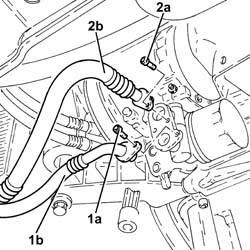
1. Undo the bolt (1a) and disconnect the cooling radiator engine oil supply pipe (1b), engine oil filter mounting side.
2. Undo the bolt (2a) and disconnect the cooling radiator engine oil return pipe (2b), engine oil filter mounting side.
Recover the engine oil which comes out in a suitable container.
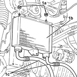
1. Undo the nuts (1a) and remove the engine oil cooling radiator (1b) complete with pipes (1c).
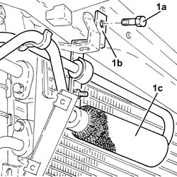
1. Undo the bolt (1a) and move the bracket (1b) complete with power assisted steering system heat exchanger pipe (1c) sideways.
Proceed with removal - 5530B10 battery - r+r.
Proceed with removal - 5530B52 Battery DRIP TRAY/SUPPORT - R.R..
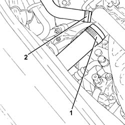
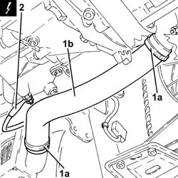
1. Loosen the band and disconnect the lower radiator coolant outlet hose from the radiator, water pump rigid inlet pipe end.
Recover the coolant using a suitable container.
2. Loosen the band and disconnect the system supply pipe from the water pump rigid inlet pipe.
1. Loosen band and disconnect the upper coolant inlet hose to the radiator thermostat side.
2. Loosen the band and disconnect the coolant return pipe to the climate control heater, thermostat side.
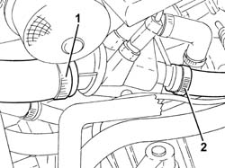
1. Loosen the band and disconnect the coolant outlet pipe from the climate control heater, water pump rigid inlet pipe side.
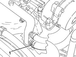
1. Loosen the band and disconnect the flexible pipe from the coolant return pipe to the engine coolant reservoir.
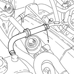
1. Loosen the band and disconnect the air intake hose from the connector on the throttle casing.
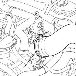
1. Undo the bolts (1a) and move the bracket (1b) complete with turbocharger vane position actuator solenoid valve (1c) away from the air filter.
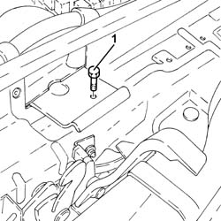
1. Undo the bolt fixing the cold air intake to the upper radiator crossmember.
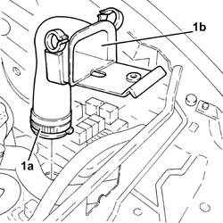
1. Loosen the band (1a) and remove the cold air intake (1b).
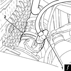
1. Disconnect the electrical connection from the air flow meter.
| Name | Connector | |
|---|---|---|
| 1 | Air flow meter | K41 |
2. Loosen the band fastening the corrugated hose to the air flow meter.
1. Disconnect the electrical connections from the engine cooling fan resistor.
| Name | Connector | |
|---|---|---|
| 1 | Engine fan adjustment resistor | O10 |
2. Disconnect the electrical connection from the engine fan motor and move the electrical wiring aside.
| Name | Connector | |
|---|---|---|
| 2 | Engine electric fan motor | N11 |
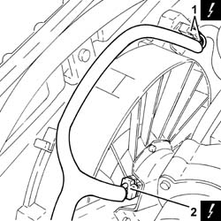
1. Remove the air filter (1a) complete with air flow meter (1b).
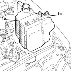
1. Disconnect the single-acting valve for the vacuum pipe from the brake servo.
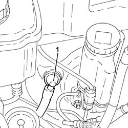
Remove the protective cap on the master cylinder bleed valve.
Connect the collection system (pipe and reservoir) to the bleed valve on the master cylinder.
Operate the clutch pedal until the brake-clutch fluid reservoir is empty.
1. Undo the connector (1a) and disconnect the pipe from the vibration damper to the operating cylinder (1b), operating cylinder side.
2. Disconnect the electrical connection from the reversing lights switch.
| Name | Connector | |
|---|---|---|
| 2 | Reversing lights switch | I20 |
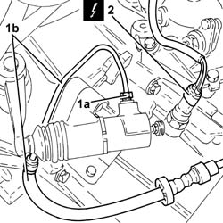
1. Disconnect the gear selector and engagement cables.
2. Undo the fastenings and move the mounting bracket complete with gear selector and engagement cables to the side.
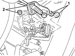
1. Undo the nuts (1a) and lift up the heater plugs control unit (1b) as much as necessary.
2. Disconnect the electrical connection from the pre-heating control unit.
| Name | Connector | |
|---|---|---|
| 2 | Plug preheating control unit | M15 |
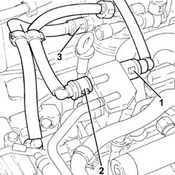
1. Disconnect the rapid attachment for the fuel return pipe to the tank, fuel return manifold pipe side.
2. Disconnect the rapid attachment for the fuel return pipe from the fuel filter, return manifold pipe side.
3. Disconnect the quick-release connector for the fuel supply pipe to the pressure pump, fuel filter side.
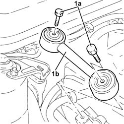
1. Undo the bolts (1a) and remove the power unit reaction rod (1b).
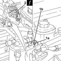
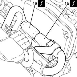
1. Disconnect the electrical connections (1a) and (1b) from the diesel electronic injection system control unit.
| Name | Connector | |
|---|---|---|
| 1a | Engine management ECU | M10A |
| Name | Connector | |
|---|---|---|
| 1b | Engine management ECU | M10B |
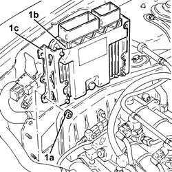
1. Unscrew the nuts (1a) and remove the diesel electronic injection system (1b) complete with slides (1c).
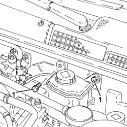
Remove the power steering fluid reservoir cap and drain the fluid using a suitable syringe.
Refit the brake fluid reservoir cap.
1. Undo the bolts securing the power steering fluid reservoir.
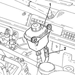
1. Move the power assisted steering fluid reservoir away, placing it as illustrated in the diagram.
2. Disconnect the rapid connector for the supply pipe from the fluid reservoir to the power assisted steering pump, reservoir side.
1. Undo the connector (1a) and disconnect the delivery pipe from pump to power steering box (1b), steering box side.
2. Release the supply pipe from the pump to the steering box from the retaining band on the power steering box.
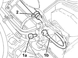
1. Undo the bolt (1a) and disconnect the flange for the coolant inlet and outlet pipes (1b) from the air conditioner compressor.
2. Undo the nut (2a) and disconnect the intermediate coupling for the pipe from the air conditioning compressor to the evaporator (2b).
Seal the disconnected connectors, using suitable plugs, to prevent humidity and impurities from entering the system.
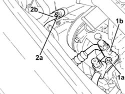
1. Undo the bolts (1a) and disconnect the coolant inlet and outlet pipes (1b) from the air conditioner condenser.
Seal the disconnected connectors, using suitable plugs, to prevent humidity and impurities from entering the system.
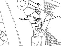
1. Undo the upper bolt fixing the engine cooling radiator to the upper crossmember.
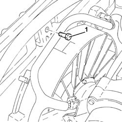
1. Loosen the bands (1a) and remove the air supply hose between the turbocharger and the heat exchanger (1b).
2. Disconnect the earth lead from the gearbox.
| Name | Connector | |
|---|---|---|
| 2 | Battery earth | C1 |
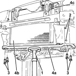
1. Position a hydraulic jack under the radiator lower crossmember.
2. Release the two buttons fixing the air duct on the supercharging air/air heat exchanger to the engine cooling radiator duct.
3. Undo the bolts securing the radiator bottom crossmember to the bodywork.
4. Lower the hydraulic jack and remove the lower radiator crossmember (4a), the climate control system condenser (4b), the engine cooling radiator (4c) and the fan.
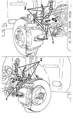
1. Unscrew the bolts securing the drive shafts to the internal differential/drive shaft.
2. Release the front brake caliper hoses, the electrical wiring for the brake pad sensor and the electrical wiring for the wheel rpm sensors (A.B.S.) from the fastenings.
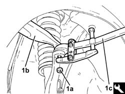
1. Undo the nuts (1a) and disconnect the front wishbones (1b) from the vertical links with the tool (1c).
| Name | Country | |
|---|---|---|
| 1c | Extractor | 1.821.169.000 |
Move the drive shafts away from the differential internal drive shaft/intermediate drive shaft.
Proceed with removal - 1076B70 exhaust pipe between pre-catalytic converter and catalytic converter - r r.
Proceed with removal - 1008A44 rear rigid mount - r r.
Position a suitable support under the power unit.
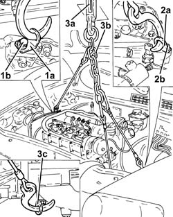
1. Fit the bracket (1a) and fasten it using the bolt (1b) as indicated in the diagram to the bracket on the engine for the reaction rod.
2. Fit the bracket (2a) and fasten to the gearbox it using the bolt (2b) as illustrated in the diagram.
3. Support the power unit using a hydraulic hoist (3a), fitted with suitable chains (3b) connected to the brackets fitted previously and to the bracket (3c) already on the gearbox.
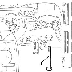
1. Undo the bolt securing timing side rigid engine support to the flexible mounting.
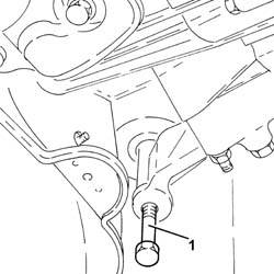
1. Undo the bolts fixing the power unit gearbox side rigid support to the flexible mounting.
Slowly lower the power unit with the hydraulic hoist until it is resting on the support positioned previously.
Take great care when removing the power unit not to damage the components fitted on the vehicle and, in particular, check that the gearbox-differential unit does not impact against the A.B.S. unit.
Refitting
Place the power unit back in the engine compartment using the hydraulic hoist.
1. Tighten the bolt fixing the power unit gearbox side rigid support to the flexible mounting.
| Fastening | Component | Ø | Value (daNm) | |
|---|---|---|---|---|
| 1 |
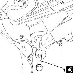
1. Tighten the bolt securing timing side rigid engine support to the flexible mounting to the recommended torque.
| Fastening | Component | Ø | Value (daNm) | |
|---|---|---|---|---|
| 1 | Bolt | ENGINE MOUNT TIMING SIDE | M12 | (Flexible mounting side) 7.9 ÷ 9.7 |
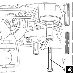
Remove the hydraulic hoist fitted with suitable chains for supporting the power unit.
Remove the brackets fitted for supporting the power unit.
Remove the support positioned previously under the power unit.
Proceed with refitting - 1008A44 rear rigid mount - r r.
Proceed with refitting - 1076B70 exhaust pipe between pre-catalytic converter and catalytic converter - r r.
Refit the drive shafts in their seating in contact with the internal differential drive shaft/intermediate drive shaft.
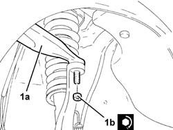
1. Connect the front upper track control arms (1a) to the steering knuckles and tighten the nuts (1b) to the specified torque.
| Fastening | Component | Ø | Value (daNm) | |
|---|---|---|---|---|
| 1b | Nut | FRONT SUSPENSION TOP LEVER | M10 | (Steering knuckle side) 4.3 ÷ 4.7 |
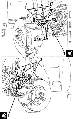
1. Tighten the bolts securing the drive shafts to the differential internal drive shaft/intermediate drive shaft to the specified torque.
| Fastening | Component | Ø | Value (daNm) | |
|---|---|---|---|---|
| 1 | Bolt | DRIVESHAFT | M10 | (Differential internal driveshaft/intermediate driveshaft side) 5.8 ÷ 7.0 |
2. Secure the front brake hoses, brake pad wear wiring and BAS inductive sensor wiring.
Connect the earth lead to the gearbox.
Refit in its seating the air supply duct between turbocharger and heat exchanger and tighten the bands.
Place the lower radiator crossmember, complete with climate control system condenser, engine cooling radiator and fan, back in its housing using the hydraulic jack.
Tighten the bolts securing the radiator bottom crossmember to the bodywork.
Remove the hydraulic jack from underneath the lower radiator crossmember.
Fit the buttons fastening the air duct on the supercharging air/air heat exchanger to the engine cooling radiator duct.
Tighten the upper bolt fastening the engine cooling radiator to the upper crossmember.
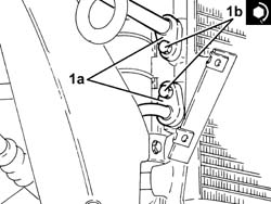
1. Connect the coolant inlet and outlet pipes (1a) from the air conditioning condenser and tighten the bolts (1b) to the recommended torque.
Replace the O-Ring seals for the connectors using green coloured seals only, resistant to R134a refrigerant fluid. Lubricate the thread of the connectors using anti-freeze.
| Fastening | Component | Ø | Value (daNm) | |
|---|---|---|---|---|
| 1b | Bolt | COOLANT SYSTEM FITTINGS | M6 | 0.9 |
1. Connect the intermediate coupling for the pipe from the air conditioning compressor to the evaporator (1a) and tighten the nut (1b) to the recommended torque.
Replace the O-Ring seals for the connectors using green coloured seals only, resistant to R134a refrigerant fluid. Lubricate the thread of the connectors using anti-freeze.
| Fastening | Component | Ø | Value (daNm) | |
|---|---|---|---|---|
| 1b | Nut | COOLANT SYSTEM FITTINGS | M6 | 0.9 |
2. Connect the flange for the coolant inlet and outlet pipes (2a) to the air conditioning compressor and tighten the bolt (2b) to the recommended torque.
| Fastening | Component | Ø | Value (daNm) | |
|---|---|---|---|---|
| 2b | Bolt | COOLANT SYSTEM FITTINGS | M10 | 2.8 ÷ 4.2 |
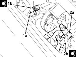
1. Secure the supply pipe from the pump to the steering box to the retaining band on the power steering box.
2. Connect the supply pipe from the pump to the power assisted steering box (2a), power assisted steering box side, and tighten the connector (2b) to the recommended torque.
| Fastening | Component | Ø | Value (daNm) | |
|---|---|---|---|---|
| 2b | Connector | PIPE BTWN PUMP + POWER STEERING BOX | M14 | (Power assisted steering box side) 3.6 ÷ 4.4 |
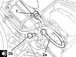
Connect the rapid connector for the supply pipe from the power steering fluid reservoir to the pump, reservoir side.
Refit in its seating the power steering fluid reservoir and secure it with its bolts.
Place the diesel electronic injection control unit complete with slides back in its housing and secure it using the nuts.
Connect the electrical connections to the diesel electronic injection control unit.
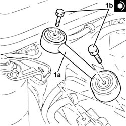
1. Place the power unit reaction rod (1a) back in its housing and fix it tightening the bolts (1b) to the recommended torque.
| Fastening | Component | Ø | Value (daNm) | |
|---|---|---|---|---|
| 1b | Bolt | REACTION ROD | M10 | 4.5 ÷ 5.5 |
Connect the quick-release connector for the fuel supply pipe to the pressure pump, fuel filter side.
Connect the rapid attachment of the fuel return pipe from the fuel filter, return manifold pipe side.
Connect the rapid attachment for the fuel return pipe to the tank, fuel return manifold pipe side.
Connect the electrical connection to the pre-heating control unit.
Place the plug preheating control unit back in its housing and secure with the relevant nuts.
Place the gear selector and engagement cables mounting bracket back in its housing and secure it.
Connect the gear selector and engagement cables.
Connect the electrical connection to the reversing lights switch.
Connect the pipe from the vibration damper to the operating cylinder, operating cylinder side and tighten the connector to the recommended torque.
| Fastening | Component | Ø | Value (daNm) |
|---|
Connect the vacuum pipe single-acting valve to the brake servo.
Replace the air filter, complete with air flow meter, in its housing.
Place the electrical wiring back in its housing and connect the electrical connection to the engine fan motor.
Connect the electrical connections to the resistor for the engine cooling fan.
Tighten the band fastening the corrugated hose to the air flow meter.
Connect the electrical connection to the air flow meter.
Place the cold air intake back in its housing and tighten the band.
Tighten the bolt securing the cold air intake to the crossmember.
Place the bracket complete with turbocharger vane position actuator solenoid valve back in its housing and fasten it using the bolts.
Connect the air inlet hose to the connector on the throttle casing and tighten the band.
Connect the flexible pipe to the rigid coolant return pipe to the engine coolant reservoir and tighten the band.
Connect the coolant outlet hose from the climate control system heater on the side of the rigid inlet pipe to the water pump.
Connect the engine coolant return pipe from the climate control system heater, thermostat side, and tighten the band.
Connect the upper coolant inlet hose to the radiator, thermostat side, and tighten the band.
Connect the system supply pipe to the water pump rigid inlet pipe and tighten the band.
Connect the lower radiator coolant outlet hose to the water pump rigid inlet pipe and tighten the band.
Proceed with refitting - 5530B52 Battery DRIP TRAY/SUPPORT - R.R..
Proceed with refitting - 5530B10 battery - r+r.
Place the bracket complete with power assisted steering system heat exchanger pipe back in its housing and fasten it using the bolt.
Place the engine oil cooling radiator complete with pipes back in its housing and fix it using the nuts.
Connect the engine oil return pipe from the cooling radiator, engine oil filter mounting side, and tighten the bolt.
Connect the engine oil supply pipe to the cooling radiator, engine oil filter mounting side, and tighten the bolt
Proceed with refitting - 1084C40 Air DUCT for engine oil cooling radiator - R.R..
Proceed with refitting - 7210E10 R.R. FRONT BUMPER.
Proceed with refitting - 7055B42 Additional FRONT WHEEL ARCH (one), left or right - R.R..
Proceed with refitting - 7055B64 Engine compartment DUST shield in front wheel arch (one), left or right - R.R..
Proceed with refitting - 7055B54 under-engine guard - r r.
Proceed with refitting - 4450B12 front or rear wheels (two) - r+r.
Refill the engine oil lubrication system - 0010T11 engine oil check level and top up.
Refill the engine cooling system with coolant - 0010T20 coolant change.
Proceed with refitting - 0010T67 hydraulic clutch system bleed air.
Fill the air conditioner coolant circuit - 5040A10 Air conditioning refrigerant CIRCUIT - Draining and Refilling.
Refill the power assisted steering circuit using the recommended fluid.
| Type | Component | Name | Qty. | |
|---|---|---|---|---|
| Oli [l] | POWER ASSISTED STEERING CIRCUIT | TUTELA GI/A | 1.2 |
The table shows the total quantity of fluid present in the power assisted steering circuit.
Bleed the power steering system as described below
With the front wheels raised off the ground, with the engine switched off turn the steering wheel to full lock, left and right, 4-5 times.
Check and, if necessary, top up the fluid level in the reservoir.
Remove the car from the ramps.
Start the engine and turn the steering wheel to full lock, left and right, 4 - 5 times.
Top up the fluid level in the reservoir.
Proceed with refitting - 1016A10 sound-proofing cover - r + r.
Proceed with refitting - 7025A14 Bonnet LID - R.R..
Proceed with refitting - 7025A12 Engine front sound insulation COVER - R.R..
Parts & tools for this job For 2000 Alfa Romeo 147
- PARTClutch kitSearch: Alfa Romeo 147 2000 clutch kit
- TOOLClutch alignment toolSearch: clutch alignment tool
- FLUIDGear oilSearch: Alfa Romeo 147 manual gearbox oil
Links open Amazon search results in a new tab. As an Amazon Associate I earn from qualifying purchases.