
Components
- Make
- Alfa Romeo
- Model
- GTV / Spider GTV and Spider (916) Factory Service Manual
- Year
- 1995–2000
- Section
- Hydraulic brake system › Components
COMPONENTS
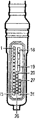
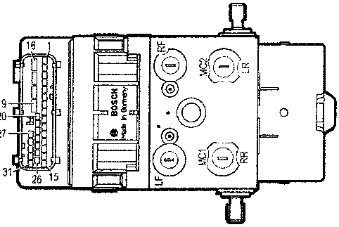
Electrohydraulic control unit
The electrohydraulic control unit comprises two sections fastened to one another: an electronic control unit and an electrohydraulic control unit.
On the basis of the signals received from the sensors and with the help of characteristic programmes mapped in its memories, the electronic control unit commands the electrohydraulic control unit.
The electrohydraulic control unit is connected to the brake pump and to the A.B.S. system components through the pipes of the braking system.
The main change with respect to the previous versions is the replacement of the three-way valves with two 2-way solenoid valves for each wheel.
Electronic control unit
The electronic control unit is formed of hybrid circuits with resistances, diodes, transistors and integrated logic circuits. The heart of the system are two CMOS microprocessors with 12K ROM which autonomously carry out the same programme and monitor one another mutually. Both receive the same input signals which each processes individually and only when the results obtained are identical, the control unit sends the operative command to the electrohydraulic control unit.
Conversely, if for example there is a fault in the wheel anti-lock system, the device cuts itself out and braking takes place conventionally: simultaneously, the fault warning light on the check panel comes on.
Operating logic
The signals (alternate or analogue) sent by the rpm sensors to the electronic control unit are transformed by the input amplifier into square wave signals.
The frequency of these signals gives the control unit the corresponding values of speed, acceleration or deceleration of the single wheels.
From the combination of the single wheel peripheral speeds, a reference speed is processed which is continuously updated and indicates the speed of the car at all times.
When the driver presses the brake pedal the wheels can each decelerate to a different extent: comparison of the peripheral speed of each wheel with the reference speed keeps the skidding of each wheel constantly under control.
If the braking force causes a wheel to skid with respect to the others, the electronic control unit sends the command to the solenoid valves of the electrohydraulic control unit to reduce the braking force on the wheel that has lost grip. This way the wheel concerned regains speed.
The memory of the electronic control unit also contains threshold acceleration and deceleration values that none of the wheels may ever exceed.
Therefore, through systematic, very rapid comparison of the wheel skidding, deceleration and acceleration values, rolling of the tyre during braking is kept under control.
As soon as the foreseen combined acceleration/deceleration and skid values are exceeded, the electronic control unit intervenes with commands to the solenoid valves of the electrohydraulic control unit, in the three adjustment phases to lower, maintain or return the pressure generated by the driver on the brake pedal to the brake calipers, bringing the braking condition to the optimum values set by the system.
These phases determine an intermittent but extremely fast adjustment cycle which is repeated until the car stops. The electronic control unit commands the different phases supplying the solenoid valves pulses with different current intensities. It also makes sure that both rear wheels are given the same braking force applicable to the rear wheel that is more subjected to locking, i.e. the one with lower grip (to ensure stability).
If a fault is detected, the wheel anti-lock device cuts out and alerts the driver by turning on the warning light on the check panel, while however ensuring operation of the conventional braking system.
The electronic control unit is informed that the driver is braking by the signal from the switch on the brake pedal. Besides controlling braking, this information is also helpful under certain particular conditions, such as for example if a sharp acceleration that makes the wheels skid is followed by heavy braking, or in the case of irregular road surfaces (humps, steps) that can involve changes in speed of the wheel due to causes not linked with the braking in progress.
Parts & tools for this job For 1995 Alfa Romeo GTV / Spider
- PARTBrake padsSearch: Alfa Romeo GTV / Spider 1995 brake pads
- TOOLBrake bleeder kitSearch: one man brake bleeder kit
- FLUIDBrake fluidSearch: brake fluid
Links open Amazon search results in a new tab. As an Amazon Associate I earn from qualifying purchases.