
Servobrake
- Make
- Alfa Romeo
- Model
- GTV / Spider GTV and Spider (916) Factory Service Manual
- Year
- 1995–2000
- Section
- Hydraulic brake system › Servobrake
‹ Prev Repair operations on the unitNext › BRANDING LOAD PROPORTIONING VALVE (up to chassis no.6023215)
33 BrakesServobrake
SERVOBRAKE
REMOVAL / REFITTING
- Empty and remove the brake - clutch fluid reservoir (see specific paragraph).
- Remove the il ABS hydraulic unit/electronic control unit(see specific paragraph).
Working in the car:
- Remove the brake pedal fastening clamp, releasing it from the servobrake control rod.
- Remove the lower part of the pedal protection detaching the two rubber fastening plugs.
- Slacken the two nuts and remove the accelerator pedal bracket.
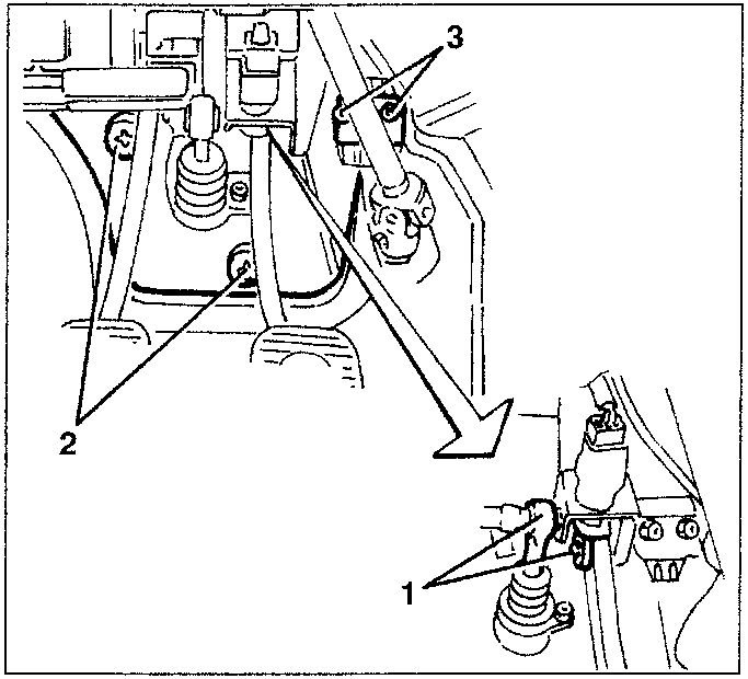
- Slacken the two nuts fastening the clutch pump, to gain access to the nut below.
- Slacken the four fastening nuts and free the servobrake pump.
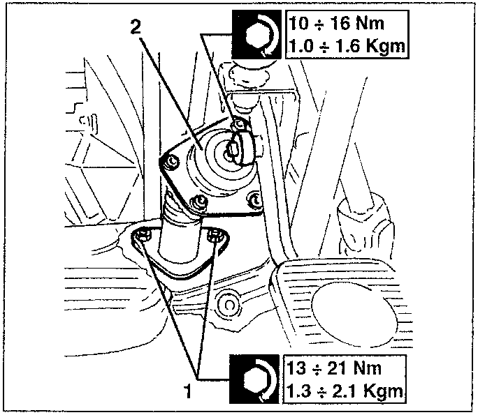
10 ÷ 16 Nm
1.0 ÷ 1.6 Kgm
13 ÷ 21 Nm
1.3 ÷ 2.1 Kgm
Working in the engine compartment
- Remove the right-hand engine compartment protection
- Disconnect the engine coolant fluid reservoir from the side panel (N.B. do NOT disconnect the pipes: it is not necessary to empty the system).
- Disconnect the two stiff delivery pipes from the brake pump.
- Disconnect the servobrake vacuum takeoff pipe
- Retrieve the servobrake together with the brake pump
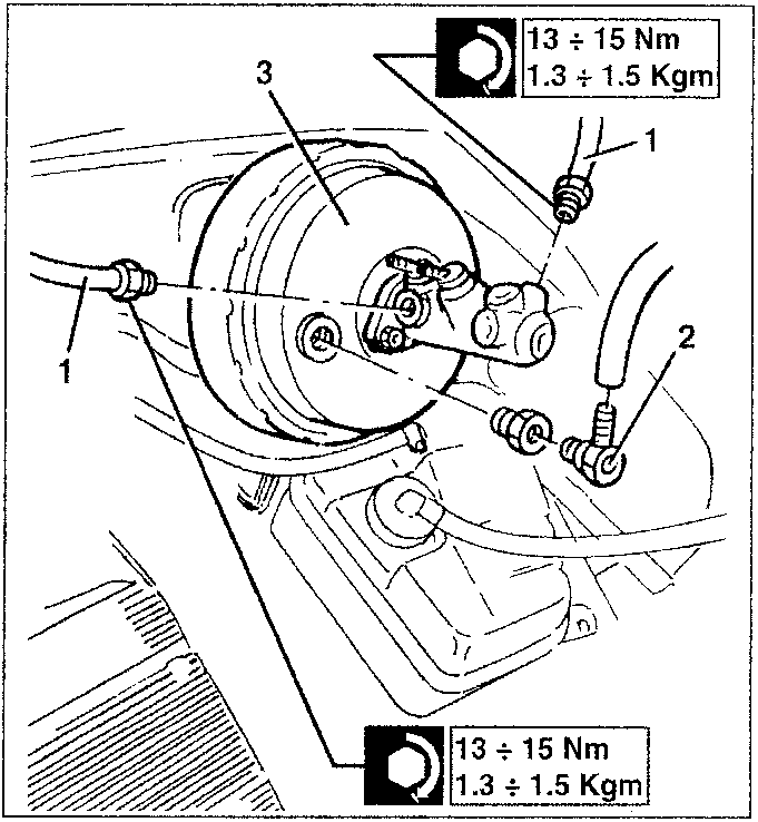
13 ÷ 15 Nm
1.3 ÷ 1.5 Kgm
13 ÷ 15 Nm
1.3 ÷ 1.5 Kgm
- If necessary, separate the unit disconnecting the pump from the servobrake; Spares however supply a single servobrake-pump unit.
When refitting bleed the air from the system; after bleeding the air, restore the correct level in the reservoir.
‹ Prev Repair operations on the unitNext › BRANDING LOAD PROPORTIONING VALVE (up to chassis no.6023215)
Parts & tools for this job For 1995 Alfa Romeo GTV / Spider
- PARTBrake padsSearch: Alfa Romeo GTV / Spider 1995 brake pads
- TOOLBrake bleeder kitSearch: one man brake bleeder kit
- FLUIDBrake fluidSearch: brake fluid
Links open Amazon search results in a new tab. As an Amazon Associate I earn from qualifying purchases.