
Air conditioning circuit
- Make
- Alfa Romeo
- Model
- GTV / Spider GTV and Spider (916) Factory Service Manual
- Year
- 1995–2000
- Section
- Heating and ventilation › Air conditioning circuit
AIR CONDITIONING CIRCUIT
This circuit is shown schematically below and mainly comprises the following components:
- a compressor fitted on the engine, which compresses the refrigerant fluid from the evaporator outlet;
- a condenser, fitted in front of the engine refrigerant fluid radiator;
- an evaporator, located in the ducting unit;
- a drier filter.
The above-mentioned parts are connected to one another by suitable pipes. On the pipe connecting the condenser to the evaporator there is a three-level pressure switch which acts as a system control and safety device, protecting the circuit against over and underpressures.
For the 2.0 T.S. 16V engine also an antifrost pressure switch is installed - before the drier filter - which prevents excessively low pressures in the circuit that might "freeze" the evaporator and block the system. From chassis no. 6023007 a 4-level pressure switch is used.
An expansion valve is inserted on the high pressure line.
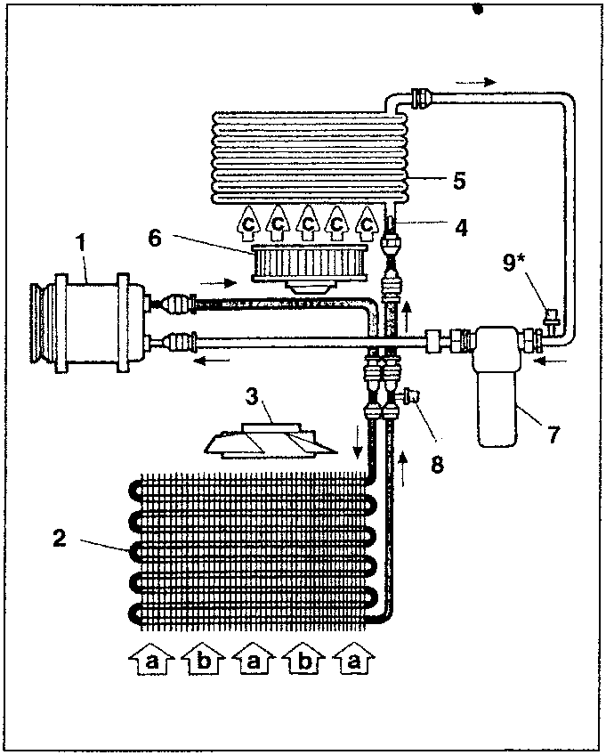
- Compressor
- Condenser
- Condenser fan
- Expansion valve
- Evaporator
- Evaporator fan
- Drier filter
- Three/four levels pressure switch
- Antifrost pressure switch
(*)2.0 T.S. 16v only
- a. Flow of air for cooling the condenser: leading from the front grille when the car is on the move.
- b. Flow of air for cooling the condenser: caused by the fan (3) when the car is at a standstill or travelling at low speed
- c. Flow of air for the evaporator: caused by the fan (5) fitted in the ducting-distributor unit.
OPERATING PRINCIPLE
The purpose of the air conditioner is to cool and dehumidify the air directed to the passenger compartment.
It works according to a common cooling cycle in the circuit of the - FREON R134a - fluid in which the changes of state (from liquid to gas and vice-versa) are exploited to absorb and release heat.
During operation, two levels of pressure are created in the circuit which are maintained on one side by the compressor and on the other side by an expansion valve at the evaporator inlet.
Two needle valves are fitted on the pipes for draining and refilling the system: one on the high pressure side and the other on the low pressure side.
The refrigerant fluid leaves the compressor as a gas at high pressure and high temperature. It then enters the condenser where it is cooled and comes out as a liquid.
The expansion valve, at the evaporator inlet lowers the pressure of the fluid thus also its temperature. The fluid, still in liquid form, enters the evaporator where it is vapourised, absorbing heat from the air pushed against its fins by the fan. The air in contact with the cold walls of the evaporator loses a high percentage of humidity which condenses and is drained off outside the car through a special drainage tube.
This way the air admitted inside the car is colder and less humid.
The fluid in a gaseous state leaves the evaporator and then passes through the drier filter which absorbs any water particles, which, if allowed to continue in the cycle could freeze and block the expansion valve, thereby reducing or nullifying the efficiency of the cycle; lastly, it returns to the compressor to resume the cycle.
Parts & tools for this job For 1995 Alfa Romeo GTV / Spider
- TOOLA/C manifold gauge setSearch: AC manifold gauge set
- TOOLUV leak detection kitSearch: AC UV leak detection kit
- PARTCabin filterSearch: Alfa Romeo GTV / Spider 1995 cabin filter
Links open Amazon search results in a new tab. As an Amazon Associate I earn from qualifying purchases.