
Composition and operation
- Make
- Alfa Romeo
- Model
- GTV / Spider GTV and Spider (916) Factory Service Manual
- Year
- 1995–2000
- Section
- Heating and ventilation › Composition and operation
Composition and operation
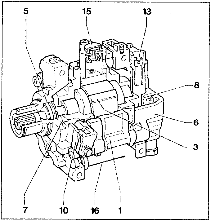
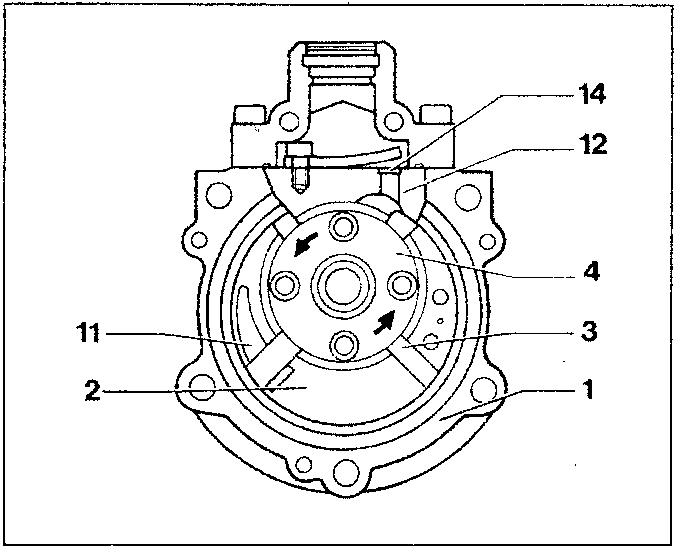
The compressor consists of a body (1) in which a chamber (2) has been made. Four blades (3) turn inside this chamber pulled by a hub (4) whose axis of rotation does not coincide with the chamber’s theoretical axis. The particular geometry of the chamber is such that as the blades turn they always contact the inner surface of the chamber: this means that differences in the compartments between one blade and the next can be obtained during rotation.
Two covers, front (5) and rear (6) are fastened to the compressor body (1) to form an intake or low pressure chamber (7) and a high pressure chamber (8) respectively. The gas taken in through union (10) on cover (5) passes through the low pressure chamber (7) and slot (11) on the body (1).
The gas is then compressed and pushed through the duct (12) in the high pressure chamber (8) and sent to the system via union (13). The reed valve (14) prevents the high pressure gas from returning to the compressor.
On the top section of the body there is a temperature sensitive contact (15) connected in series to an electromagnetic joint. When the temperature reaches dangerous limits (over 160°C), this contact (15) cuts out the compressor: it activates it again if the temperature falls below 140°C.
This way operation is prevented under dangerous conditions such as lack of fluid or oil.
The pressure regulator (16) in the lower section of the compressor serves to adjust the flow rate of the fluid in the compressor, as described on the next page.
Parts & tools for this job For 1995 Alfa Romeo GTV / Spider
- TOOLA/C manifold gauge setSearch: AC manifold gauge set
- TOOLUV leak detection kitSearch: AC UV leak detection kit
- PARTCabin filterSearch: Alfa Romeo GTV / Spider 1995 cabin filter
Links open Amazon search results in a new tab. As an Amazon Associate I earn from qualifying purchases.