
Alternator and components
- Make
- Fiat
- Model
- 500 Factory Service Manual
- Year
- 2007–2024
- Section
- Current generation › Alternator and components
ALTERNATOR AND COMPONENTS
COMPOSITION
The alternator is a rotary machine that transforms mechanical energy into electrical energy.
The following diagram shows a cross section of the alternator.
Version for 1.2 8V Petrol engine.
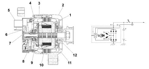
1. Rotor electromagnetic circuit
2. Control-side support
3. Rectifier-side support
4. Assembly bolts
5. Heat shield cap
6. Regulation assembly
7. Manifold
8. Rectifier-side bearing
9. Rectifier-side inner fan
10. Stator electronic circuit
11. Control-side inner fan
12. Control-side bearing
Version for 1.3 16V Multijet engine.
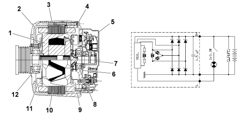
1. Rotor electromagnetic circuit
2. Control-side support
3. Rectifier-side support
4. Assembly bolts
5. Heat shield cap
6. Regulation assembly
7. Manifold
8. Rectifier-side bearing
9. Rectifier-side inner fan
10. Stator electronic circuit
11. Control-side inner fan
12. Control-side bearing
Version for 1.4 16V Petrol engine.
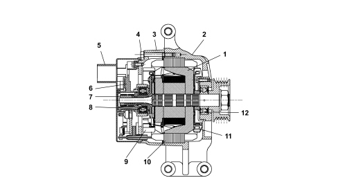
1. Rotor electromagnetic circuit
2. Control-side support
3. Rectifier-side support
4. Assembly bolts
5. Heat shield cap
6. Regulation assembly
7. Manifold
8. Rectifier-side bearing
9. Rectifier-side inner fan
10. Stator electronic circuit
11. Control-side inner fan
12. Control-side bearing
As with all electrical machines, it is made up of two basic parts: inductor (rotor) and field winding (stator).
The rotor for an alternator with internal ventilation is illustrated in the diagram below.
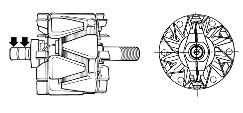
Rotor
The rotor consists of a cylindrical magnetic core, concentric to the driveshaft, with a toroidal coil winding and two opposing magnetic impellers which are magnetized by the winding located in the core itself.
The impellers have six claw-shaped poles that fit between one another to produce six North poles and six South poles in alternation. The result is a single rotor winding which produces the e.m.f. for all the partial magnetic circuits.
Stator
The following diagram shows the stator.
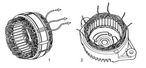
1. Star connection stator
2. Triangle connection stator
It consists of a ring-shaped pack joined by two or more axial seams electrically welded on the outer part. It is normally equipped with thirty-six grooves which contain a three-phase winding made from copper wire insulated with vinyl acetate and connected, as necessary, in a star or triangle formation.
Rectifier bridge
The rectifier bridge is illustrated in the diagram.
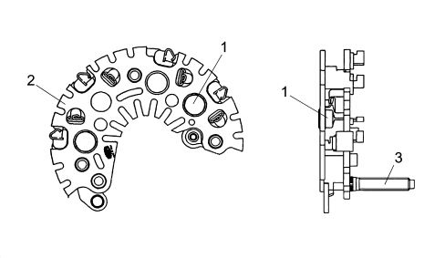
1. Zener type power diode
2. Dissipator plate
3. Alternator B + terminal
Specifications of the bridge
The bridge consists of:
- Zener diodes.
- Diodes press-fitted in the dissipator plates and electrically welded to the terminals for connection to the phases.
- Sheared dissipator plates.
- Large dimension dissipators.
- Phase insulation until the connection with the bridge via a rubber cable duct.
- Limitation of excess voltage in the case of + battery load disconnection guaranteed by zener diodes.
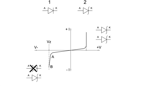
1. Normal diode
2. Zener diode
Zener diodes
The characteristic of both diodes, if polarized directly, is that they pass the current from the anode to the cathode (V+ I+): then a zener diode behaves like a normal silicon diode.
If inversely polarized, the current does not initially pass from the cathode to the anode up to value Vz (V-I-).
Beyond value Vz the normal diode is destroyed; the zener diode, on the other hand, continues to operate normally because its resistance in these conditions decreases sharply. Zener diodes are therefore voltage stabilizer diodes. In the car it is used with voltages of between 4.7 and 24 Volts. It is one of the most important components in the regulator unit.
It is often used for protection against polarity inversion or as protection against excess voltage.
SPECIFICATIONS OF INTERNAL VENTILATION ALTERNATORS
The main feature of this type of alternator, with a 115 mm stator diameter, is having dual internal ventilation with the vanes at an angle to guarantee the maximum flow of air and limit noise at the same time.
For the same power output, alternators with internal ventilation are smaller and lighter than types with external ventilation, thereby satisfying current application requirements (there is always less space in engine compartments). In addition to this, in terms of quality, reliability and durability, these alternators meet higher standards than the best competition currently on the market.
In-depth studies and research have made it possible to introduce measures in production to reduce noise limits produced by various components (fluid dynamics, magnetics, mechanics).
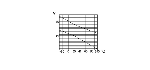
Typical voltage curve
The following graph shows the typical curve of regulator voltage for alternators associated with 1.2 8V and 1.4 16V petrol engines.
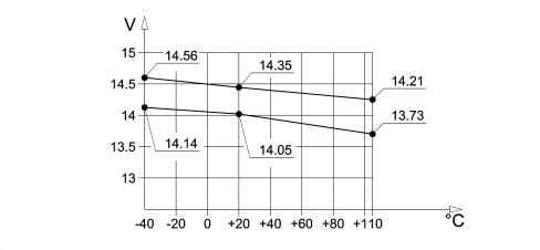
The following graph shows the typical curve of regulator voltage for alternators associated with the 1.3 Multijet engine.
OPERATION
With the alternator still with the ignition key in the MAR position, the Dashboard Node lights up the battery warning light in the instrument panel (NQS) and sends a power supply to the voltage regulator built into the alternator via terminal D+.
In these conditions the excitation circuit (rotor) is enabled to earth by the regulator electronics.
With the alternator rotating through the effect of the variation of the rpm and the magnetic field, a three-phase alternating voltage is produced in the electrical circuit (stator), which, rectified by the diode bridge, can exit terminal B+.
The Dashboard Node controls the efficiency of the alternator recharging system by measuring the voltage signal coming from terminal D+ of the alternator.
The check on connection D+ is only carried out at Key-ON until the voltage at D+ is less than 5.5V? 0.2 V the Dashboard Node signals the insufficient recharging status to the Instrument Panel Node, which in turn lights the associated warning light, if the voltage at D+ is greater than 5.5V ? 0.2 V, the NPL gives the correct recharging signal.
If the voltage at D+ goes under the threshold of 4.5V ? 0.2 V, the NPL gives the insufficient recharging signal.
If there is no recharging signal or it is irregular, before completely dismantling the alternator, carry out the following checks:
- check the tension of the belt;
- check the tightening of the nut on the alternator positive terminal (B+), making sure that the washer is present;
- check the tightening of the nut on the excitation terminal (D+), making sure that the washer is present;
- check the tightening of the nuts on the positive node in the engine compartment;
- check the tightening of the bolts securing the negative terminal to the body;
- check that the battery terminals are clean and correctly tightened.
Parts & tools for this job For 2007 Fiat 500
- TOOLBattery testerSearch: car battery tester
- TOOLDigital multimeterSearch: automotive digital multimeter
- TOOLBattery terminal cleanerSearch: battery terminal cleaner
Links open Amazon search results in a new tab. As an Amazon Associate I earn from qualifying purchases.