
Crankshaft
- Make
- Fiat
- Model
- 500 Factory Service Manual
- Year
- 2007–2024
- Section
- Crankshaft and flywheel › Crankshaft
CRANKSHAFT
Made from induction hardened cast iron. Resting on five main bearings with interposed half-bearings divided into size categories.
The crankshaft endfloat is adjusted by two half-rings housed on the middle main bearing.
Eight counterweights arranged at 180° accurately balance the crankshaft rotating masses.
A channel running along the length of the shaft lubricates the main journals and crankpins.
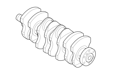
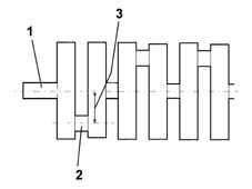
The crankshaft consists of:
- main journals (1), through which it rotates on main bearings with bearings (washers) in between;
- crank pins (2) above which the connecting rod big ends are hinged;
- crank arms (3), with height equal to half the length of the travel, which join the main journals and the crank pins.
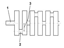
In addition, the shaft is also prepared for:
- the fitting of the flywheel;
- fitting the gear which transmits power to the timing system components by means of a toothed belt.
OPERATION
The crankshaft consists of:
- main journals (1), through which it rotates on main bearings with bearings (washers) in between;
- crank pins (2) above which the connecting rod big ends are hinged;
- crank arms (3), with height equal to half the length of the travel, which join the main journals and the crank pins.
OPERATION
There are two types of firing order: 1, 2, 4, 3 or 1, 3, 4, 2; the best known one is firing order 1, 3, 4, 2 because the centrifugal forces and the inertia forces are better balanced.
This is steel and rests on five main bearings. Shaft end float is governed by two half-rings housed in the central main bearing.
Eight counterweights accurately balance the crankshaft rotating masses.
A set of channels run along the length of the crankshaft to lubricate the main journals and crankpins.
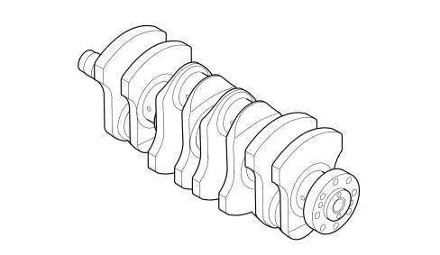
CONSTRUCTION SPECIFICATIONS
Made from induction hardened cast iron. Resting on five main bearings with interposed half-bearings divided into size categories.
The crankshaft endfloat is adjusted by two half-rings housed on the middle main bearing.
Eight counterweights arranged at 180° accurately balance the crankshaft rotating masses. A channel running along the length of the shaft lubricates the main journals and crankpins.
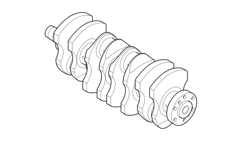
COMPOSITION
The crankshaft consists of:
- main journals (1), through which it rotates on main bearings with bearings (washers) in between;
- crank pins (2) above which the connecting rod big ends are hinged;
- crank arms (3), with height equal to half the length of the travel, which join the main journals and the crank pins.
In addition, the shaft is also prepared for:
- the fitting of the flywheel;
- fitting the gear which transmits power to the timing system components by means of a toothed belt.
OPERATION
The crankshaft is the component that transforms the alternating rectilinear motion of the piston into a rotary motion by means of the connecting rod.
It is subject to forces that vary sharply in intensity and direction and must therefore be sufficiently resistant.
Its shape depends on the:
- number of cylinders
- engine type (in line, v-configuration, w-configuration, etc.)
- number of main bearings
- number of strokes (2 stroke or 4 stroke)
To prevent vibrations which can be damaging to the engine, the crankshaft should be balanced both statically and dynamically. The vibrations are due to:
- centrifugal forces produced by the masses equipped with a rotary motion (crank pins, connecting rod big end, 1/3 of the weight of the connecting rod, crank arms);
- inertia forces produced by the masses equipped with an alternating rectilinear motion (piston, piston pin, 2/3 of the weight of the connecting rod).
A shaft is statically balanced when, resting on two mounts, it remains balanced irrespective of the rotation position.
A shaft is dynamically balanced when, supported between two points on the rotation axis and made to turn, it transmits a reaction equal to half its own weight on each support.
The addition of counter-weights in appropriate positions balances the crankshaft statically or dynamically.
However, it is not enough to balance the crankshaft in order to dampen engine vibrations; the motion must also be made uniform by both offsetting the working cycles (following a given firing order) and providing the shaft with a suitable flywheel.
In engines with several cylinders, the firing order is achieved by offsetting the cranks to an angle of:
α = 180° x t/i
where:
- t = engine strokes
- i = number of cylinders
In our case (4 stroke engine with 4 cylinders).
The crank offset angle is equal to:
α = 180 x 4/4 = 180°
The cranks are arranged on the same plane and parallel, two by two.
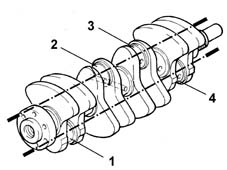
There are two types of firing order: 1, 2, 4, 3 or 1, 3, 4, 2; the best known one is firing order 1, 3, 4, 2 because the centrifugal forces and the inertia forces are better balanced.
Parts & tools for this job For 2007 Fiat 500
- PARTEngine gasket setSearch: Fiat 500 2007 engine gasket set
- TOOLTorque wrenchSearch: 3/8 inch torque wrench
- TOOLFeeler gauge setSearch: feeler gauge set
Links open Amazon search results in a new tab. As an Amazon Associate I earn from qualifying purchases.