
Checking the resistance
- Make
- Fiat
- Model
- Bravo /Brava (182) Factory Service Manual
- Year
- 1995–2001
- Section
- Fuel system (1998 20v) › Checking the resistance
Checking the resistance
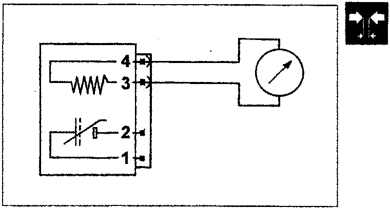
The resistance of the sensor heater can be measured by disconnecting the connector and connecting an ohmmeter as shown in the diagram.
Resistance: 4.5 ± 0.5 ohm at 20 °C
CHARCOAL FILTER AND FUEL VAPOUR CUT OUT SOLENOID VALVE
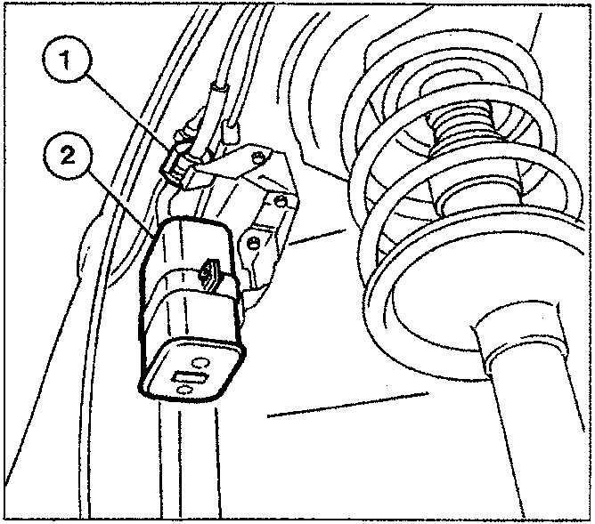
The charcoal filter and the solenoid valve are located in the right wheel arch.
For the description of the charcoal filter refer to the Fuel System section for the 1581 16V engine.
- Vapour cut out solenoid valve
- Charcoal filter
Vapour cut out solenoid valve (0.280.142.300)
The function of this valve is to control the quantity of petrol vapours drawn in by the active charcoal filter and directed to the inlet manifold by means of the electronic control unit.
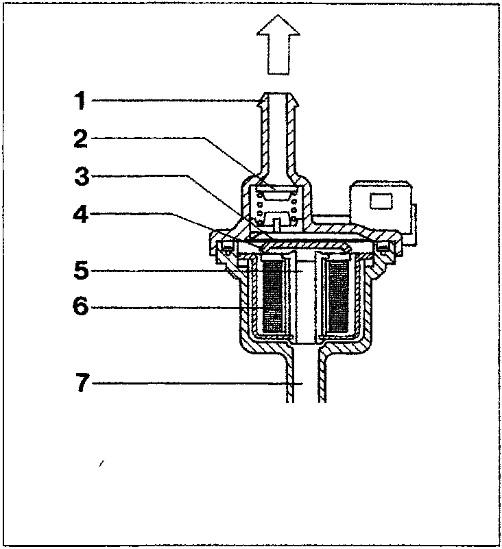
If this valve is not supplied it is in the open position; if the key is turned to the ON position, it closes preparing for operation. In effect, if energized the solenoid valve (6) attracts the shutter (4) which, overcoming the spring (3) loading, closes the port (5) preventing the flow of petrol vapours.
The operation is controlled by the electronic control unit as follows:
- during starting the solenoid valve remains closed, preventing the petrol vapours from excessively enriching the mixture;
- when the engine has been started up, the electronic control unit sends a signal to the solenoid valve which modulates the opening.
In this way the control unit controls the quantity of petrol vapours sent to the inlet, thereby preventing considerable variations (above all during idling) in the mixture strength.
NOTE The solenoid valve must be fitted correctly: the arrow on its casing should be facing the vacuum inlet on the inlet manifold.
- Inlet union
- One-way valve
- Spring
- Shutter
- Outlet port
- Solenoid valve
- Outlet union
Parts & tools for this job For 1995 Fiat Bravo
- PARTFuel filterSearch: Fiat Bravo 1995 fuel filter
- TOOLFuel pressure test kitSearch: fuel pressure test kit
- TOOLFuel line disconnect toolSearch: fuel line disconnect tool
Links open Amazon search results in a new tab. As an Amazon Associate I earn from qualifying purchases.