
Location of injection/ignition system components
- Make
- Fiat
- Model
- Bravo /Brava (182) Factory Service Manual
- Year
- 1995–2001
- Section
- Fuel system (1998 20v) › Location of injection/ignition system components
‹ Prev Diagram showing engine exhaust assemblyNext › Wiring diagram showing injection/ignition system
10 EngineLocation of injection/ignition system components
LOCATION OF INJECTION/IGNITION SYSTEM COMPONENTS
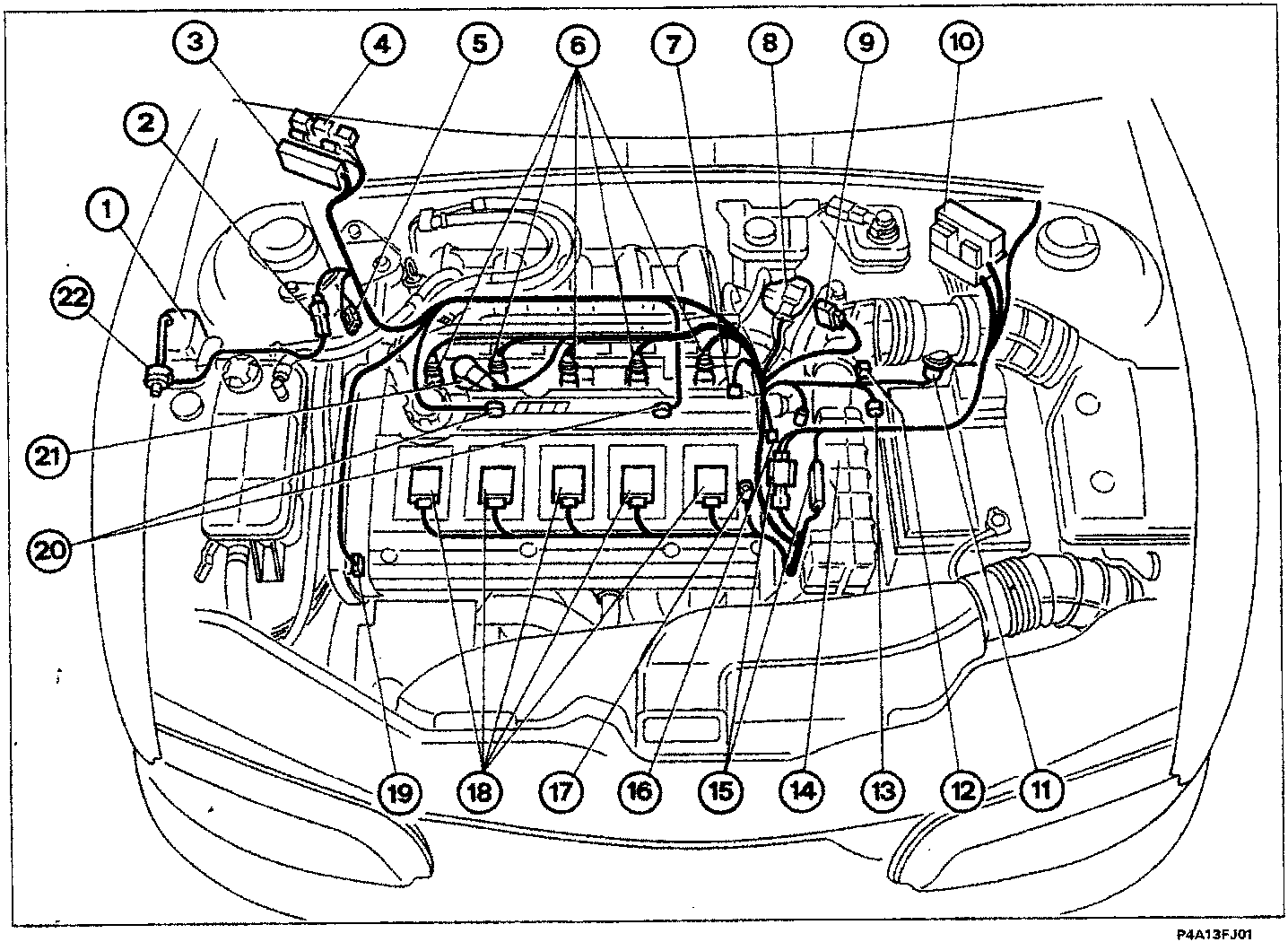
Key
- Charcoal filter
- Fuel vapour solenoid valve connection
- Injection/ignition control unit
- Fuses and relays
- Diagnostic socket
- Injectors
- Rpm sensor
- Engine idle speed actuator
- Butterfly valve position sensor
- General system protective fuse
- Flow meter
- Air temperature sensor
- Vehicle speed sensor
- Lambda sensor
- Join between front cable and injection cable
- Coolant temperature sensor
- Earth connection
- Ignition coils
- Timing sensor
- Detonation sensor
- Phase transformer solenoid valve
- Fuel vapour solenoid valve
‹ Prev Diagram showing engine exhaust assemblyNext › Wiring diagram showing injection/ignition system
Parts & tools for this job For 1995 Fiat Bravo
- PARTSpark plugsSearch: Fiat Bravo 1995 spark plugs
- TOOLSpark plug socketSearch: spark plug socket
- TOOLSpark plug gap toolSearch: spark plug gap tool
Links open Amazon search results in a new tab. As an Amazon Associate I earn from qualifying purchases.