
Diagram showing fuel supply circuit
- Make
- Fiat
- Model
- Bravo /Brava (182) Factory Service Manual
- Year
- 1995–2001
- Section
- Fuel system (1998 20v) › Diagram showing fuel supply circuit
‹ Prev Diagram showing information entering/leaving the injection/ignition system control unit and sensors/actuatorsNext › Diagram showing air intake circuit
10 EngineDiagram showing fuel supply circuit
DIAGRAM SHOWING FUEL SUPPLY CIRCUIT
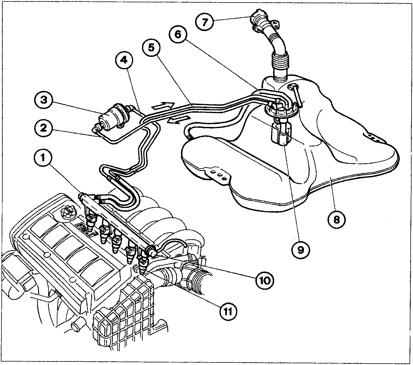
- Fuel supply manifold
- Supply pipe from the tank to the filter
- Filter
- Supply pipe from filter to injectors
- Return pipe
- Breather pipe
- Filler with ventilation and safety valve
- Tank
- Electric pump
- Pressure regulator
- Injectors
NOTE Given the special shape of the tank, when fuel is being introduced an air pocket tends to form in the lower part preventing it from being filled completely; the pipe (6) allows the air to flow from the bottom thereby enabling the tank to be filled completely.
‹ Prev Diagram showing information entering/leaving the injection/ignition system control unit and sensors/actuatorsNext › Diagram showing air intake circuit
Parts & tools for this job For 1995 Fiat Bravo
- TOOLDigital multimeterSearch: automotive digital multimeter
- PARTAssorted fuse kitSearch: car fuse assortment kit
- TOOLWire crimper and connector kitSearch: wire crimper connector kit
Links open Amazon search results in a new tab. As an Amazon Associate I earn from qualifying purchases.