
Injectors (0.280.150.443)
- Make
- Fiat
- Model
- Bravo /Brava (182) Factory Service Manual
- Year
- 1995–2001
- Section
- Fuel system (1998 20v) › Injectors (0.280.150.443)
INJECTORS (0.280.150.443)
The double jet type injectors are fitted on the inlet manifolds, immediately before the inlet valve. These injectors are specifically for engines with 4 valves per cylinder, making it possible to direct the jets towards the two inlet valves.
The jets of fuel at a differential pressure of 3 bar which leave the injector are instantly atomized forming two cones of about 10° each.
The operation of the injectors is the «sequential timed» type, i.e. the five injectors are operated according to the engine cylinder inlet sequence, whilst the supply can already start for each cylinder during the ex-pansion stroke until the inlet stroke has already begun.
The injectors are fixed by the fuel manifold which presses them into their housings in the inlet manifolds. In addition they are anchored to the fuel manifold by means of «safety clips». Two rubber seals (10) and (11) ensure the seal for the inlet manifold and the fuel manifold.
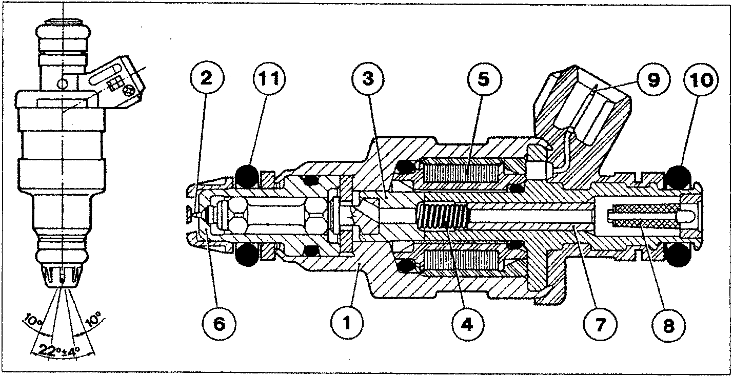
- Injector casing
- Needle
- Magnetic core
- Coil spring
- Winding
- Injector nose
- Adjustable spring pusher
- Fuel filter
- Electrical connection socket
- Fuel seal
- Vacuum seal
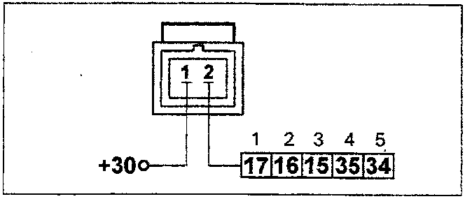
Wiring connector
NOTE The numbers indicate the corresponding control unit pins arranged in the order of the number of cylinders.
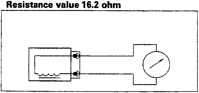
Checking the resistance
The resistance of the injector can be measured by disconnecting the connector and connecting an ohmmeter as shown in the diagram.
Resistance value 16.2 ohm
Parts & tools for this job For 1995 Fiat Bravo
- PARTFuel filterSearch: Fiat Bravo 1995 fuel filter
- TOOLFuel pressure test kitSearch: fuel pressure test kit
- TOOLFuel line disconnect toolSearch: fuel line disconnect tool
Links open Amazon search results in a new tab. As an Amazon Associate I earn from qualifying purchases.