
Recovery
- Make
- Fiat
- Model
- Bravo /Brava (182) Factory Service Manual
- Year
- 1995–2001
- Section
- Fuel system (1998 20v) › Recovery
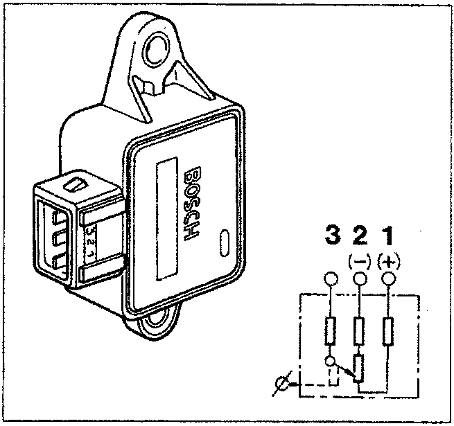
Recovery
If the sensor fails, the control unit establishes the following parameters:
Butterfly opening angle = 10°
idle state: air flow rate < 12.8 m3/h;
exit from idle state: air flow rate > 8 m3/h;
full load state: engine load > 6,5 ms and simultaneous speed > 2000 RPM;
exit from full load state: engine load < 6,5 ms or speed < 2000 RPM.
Additional provisions
The engine idle speed gradual decrease (dashpot) and idle self-adjustment strategies are stopped.
BUTTERFLY VALVE POSITION SENSOR (0.280.122.001)
The sensor is made up of a potentiometer inserted in a plastic container which has two fins, in which there are two openings WITHOUT SLOTS which have the function of ensuring the anchorage and the positionining of the sensor in relation to the butterfly valve. A three pin socket in the container guarantees the electrical connection with the electronic control unit.
During operation, the injection/ignition control unit provides the potentiometer with a supply of 5 Volts at pins (1) and (2). There is a voltage at pin 3 which is inversely proportional to the opening position of the butterfly valve. According to the voltage sent by pin 3 the control unit recognizes the opening condition for the butterfly valve and suitably corrects the mixture strength.
With the butterfly closed an electrical voltage signal of around 0.5 Volts reaches the control unit which recognizes the idle and cut off conditions (distinguishing them on the basis of the engine speed).
The potentiometer automatically recognizes the butterfly idle position by means of a "self-adjustment" function. This eliminates the adjustment operations and makes it possible to allow for any wear which may occur for the butterfly closure position.
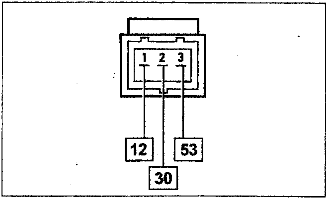
Wiring connector
NOTE The numbers indicate the corresponding control unit pins
Parts & tools for this job For 1995 Fiat Bravo
- PARTFuel filterSearch: Fiat Bravo 1995 fuel filter
- TOOLFuel pressure test kitSearch: fuel pressure test kit
- TOOLFuel line disconnect toolSearch: fuel line disconnect tool
Links open Amazon search results in a new tab. As an Amazon Associate I earn from qualifying purchases.