
Electrical features
- Make
- Fiat
- Model
- Bravo /Brava (182) Factory Service Manual
- Year
- 1995–2001
- Section
- Fuel system (1998 20v) › Electrical features
10 EngineElectrical features
Electrical features
Primary winding inductance................... 3 mH
Primary winding resistance.................... 0,4 Ω
Interference resistance....................... 1 KΩ
Diagram showing electrical connections
- Operating signal
- Primary winding
- Secondary winding
- Supply via ignition switch
- Single coil
- Electronic control unit
- Spark plug
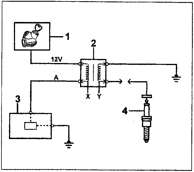
- Supply via ignition switch
- Single coil
- Electronic control unit
- Spark plug
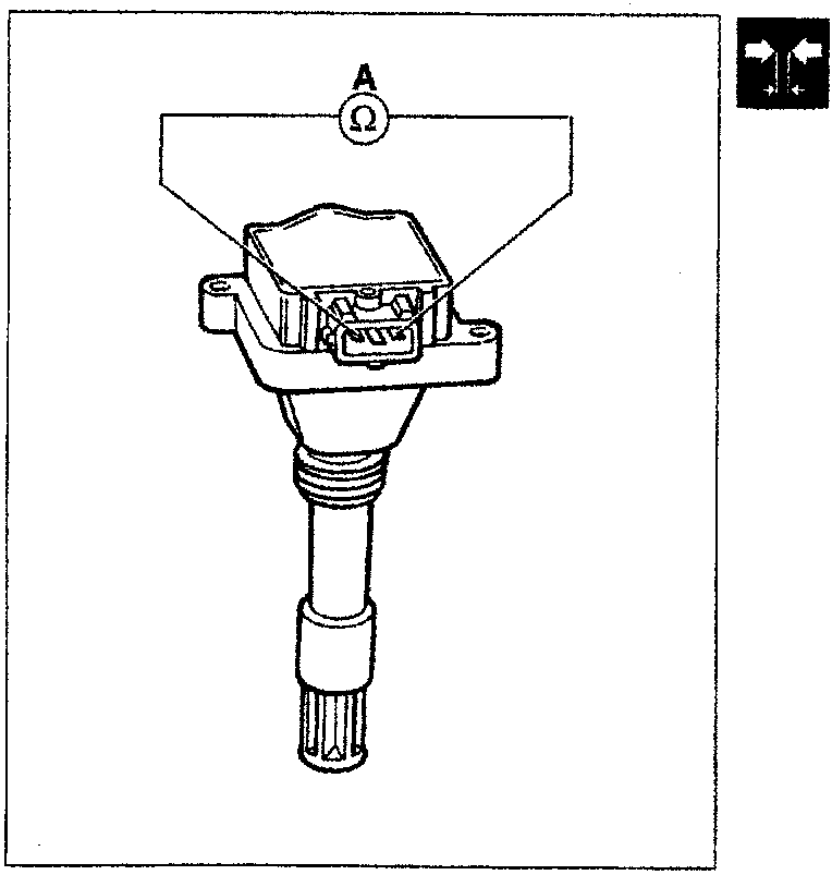
Checking coil circuit resistance
A. Primary circuit
The resistance is checked by connecting an ohmmeter to the connector outer pins, as shown in the diagram.
Primary resistance: 0.4 ohm
Wiring connector
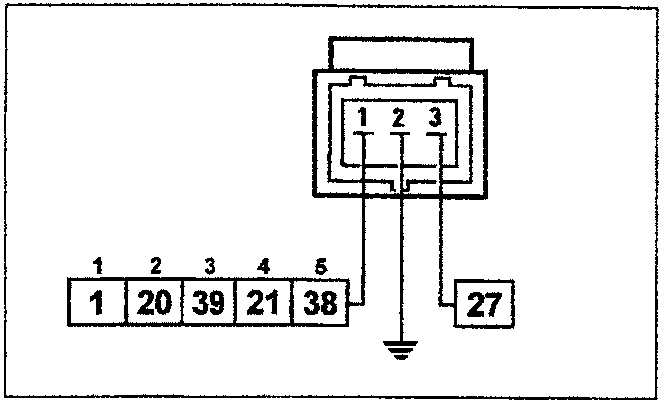
The numbers indicate the corresponding pins for the control unit arranged in the order of the number of cylinders.
Parts & tools for this job For 1995 Fiat Bravo
- TOOLDigital multimeterSearch: automotive digital multimeter
- PARTAssorted fuse kitSearch: car fuse assortment kit
- TOOLWire crimper and connector kitSearch: wire crimper connector kit
Links open Amazon search results in a new tab. As an Amazon Associate I earn from qualifying purchases.