
Speedometer sensor
- Make
- Fiat
- Model
- Bravo /Brava (182) Factory Service Manual
- Year
- 1995–2001
- Section
- Fuel system (1998 20v) › Speedometer sensor
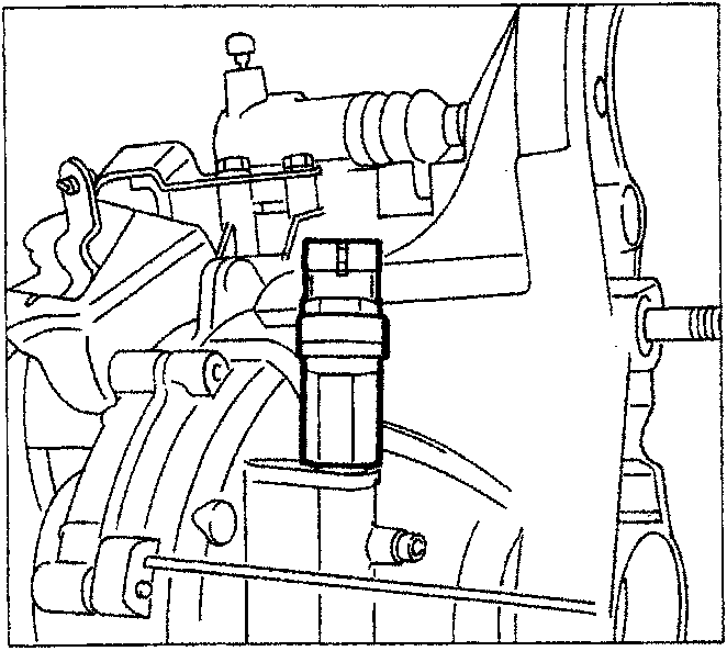
SPEEDOMETER SENSOR
The speedometer sensor (vehicle speed sensor) it is composed of a Hall effect sensor and is located at the differential outlet.
The sensor transmits a signal to the control unit where the frequency varies according to the speed of the vehicle.
The control unit uses this information to improve the management of the engine idle adjustment actuator and for the CUT-OFF strategy.
The speedometer sensor signal is also processed to calculate and memorize the mileage travelled in the control unit; this information can be read using the Fiat/Lancia Tester.
PHASE TRANSFORMER
In order to achieve a good compromise between the high performance in terms of power at high speeds and good torque at low speeds, a phase transformer (electronically and hydraulically operated) is fitted for the inlet camshaft.
This device makes it possible to alter the timing diagram (inlet phase) according to the engine load conditions; this parameter is processed by the MOTRONIC control unit on the basis of the electrical signals received by the air flow meter and the rpm sensor and sent to the phase transformer solenoid valve.
The construction of the device involves a main assembly fitted on the inlet camshaft which has the task of altering the angular position of the actual shaft in relation to the drive pulley.
In addition there is a valve, operated by an electro-magnet, both of which are on the inlet manifold and connected hydraulically to the main assembly by appropriate ducts.
The operating principle is as follows:
- with the temperature of the coolant below 40 °C and when the engine is idling or the speed exceeds 4800 rpm, the electro-magnet (1) is de-energized, therefore the valve (2) thrust by the opposing spring (3) remains raised not allowing the oil which is arriving from the duct (A) to reach the transformer.
In this case the timing of the inlet valves remains unaltered.
With the temperature of the coolant above 40 °C and with the engine speed above idle and below 4800 rpm with the butterfly angle greater than about 8°, the electro-magnet (1) is energized, thereby thrusting the valve (2) downwards. In this position the oil, coming from the duct (A), enters the piston chamber (B) and from here flows via a special opening into the duct (C) inside the latter.
The oil can only leave the above mentioned duct via the upper port (in contact with duct (D) supplying oil to the transformer) because with the valve (2) lowered, the lower port is not in contact with the discharge duct (E).
The oil reaches the chamber (G) through ducts (D) and (F) moving the piston (4) axially towards the engine; because this piston has helical teeth on the outside this axial movement causes it to rotate in a clockwise direction (as seen from the timing side).
This rotation is transmitted, by means of a straight toothed splied profile, to the pinion (5) which, bolted onto the threaded end of the camshaft (6), transmits the rotation to the shaft, thereby varying the timing of the inlet valves by an advance of 9°.
When the electro-magnet is de-energized, the valve (2) returns to the original position, interrupting the flow of oil under pressure to the chamber (G), but allowing the return of the oil to the exhaust, thanks to the force of the opposing spring (7).
Parts & tools for this job For 1995 Fiat Bravo
- TOOLOBD2 scannerSearch: OBD2 scanner
- TOOLDigital multimeterSearch: automotive digital multimeter
- TOOLBack-probe test leadsSearch: back probe test leads
Links open Amazon search results in a new tab. As an Amazon Associate I earn from qualifying purchases.