
Description of the operation
- Make
- Fiat
- Model
- Bravo /Brava (182) Factory Service Manual
- Year
- 1995–2001
- Section
- Fuel system (1998 20v) › Description of the operation
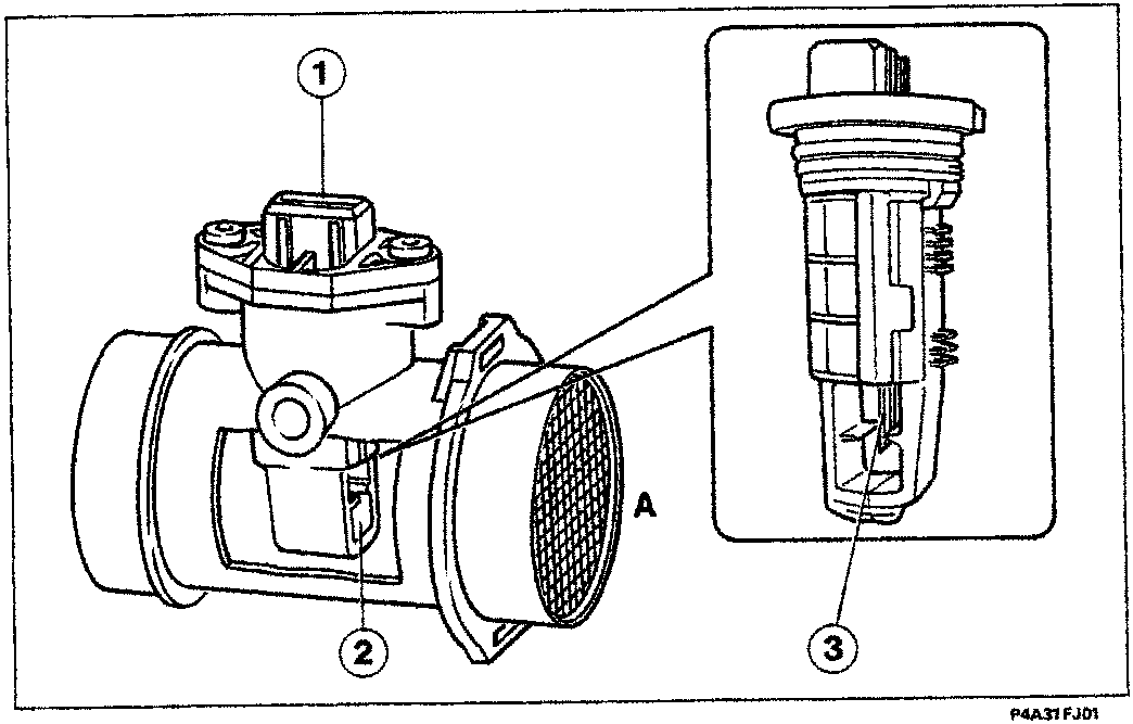
- Connector
2. Measuring duct
3. Hot film sensor
A= Air intake
NOTE This flow meter directly measures the mass of air (and not the volume as on previous versions) thereby dispensing with the problems of temperature, altitude, pressure, etc.
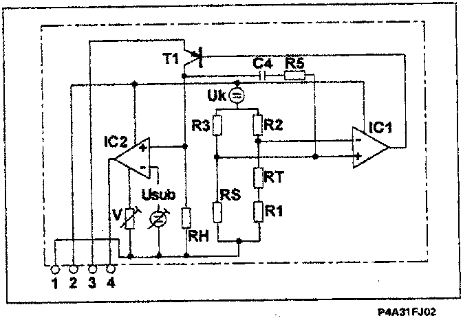
Description of the operation
The Wheatstone bridge (made up of R3, R2, Rs, Rt+R1) is balanced when the Rs is at about 120 °C above the temperature of the air. The air which passes through the diaphragm removes heat from the Rs, therefore the bridge is unbalanced. This situation is detected by the circuit at IC1 which controls the transistor T1 in a manner which is proportional to the bridge imbalance and as a result more current is passed through Rh to heat Rs and therefore restore the balance for the bridge. The circuit IC2 measures the current which passes through Rh. This current makes it possible to keep the bridge balanced and therefore proportional to the mass of air which passes through the air flow meter.
Recovery
In the absence of a simultaneous error at the butterfly potentiometer, the idle engine load is calculated according to the speed if the engine is idling, otherwise a fixedengine load is allocated. If there is a simultaneous error at the butterfly potentiometer, the engine load and advance values are allocated according to a table depending on the number of revs.
Additional provisions
Locking the self-adjustment of the mixture strength and idle at current values.
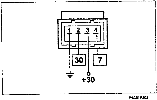
Wiring connector
NOTE The numbers indicate the corresponding control unit pins.
Parts & tools for this job For 1995 Fiat Bravo
- PARTFuel filterSearch: Fiat Bravo 1995 fuel filter
- TOOLFuel pressure test kitSearch: fuel pressure test kit
- TOOLFuel line disconnect toolSearch: fuel line disconnect tool
Links open Amazon search results in a new tab. As an Amazon Associate I earn from qualifying purchases.