
Diagram showing air intake circuit
- Make
- Fiat
- Model
- Bravo /Brava (182) Factory Service Manual
- Year
- 1995–2001
- Section
- Fuel system (1998 20v) › Diagram showing air intake circuit
10 EngineDiagram showing air intake circuit
DIAGRAM SHOWING AIR INTAKE CIRCUIT
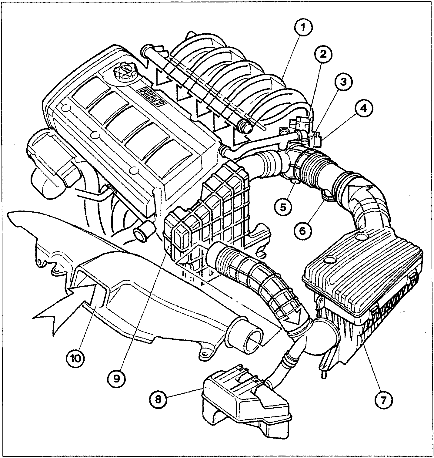
- Inlet manifold
- Engine idle speed actuator
- Butterfly casing
- Butterfly valve position sensor
- Air temperature sensor
- Flow meter
- Air filter
- Lower resonator
- Upper resonator
- Inlet opening
Parts & tools for this job For 1995 Fiat Bravo
- TOOLDigital multimeterSearch: automotive digital multimeter
- PARTAssorted fuse kitSearch: car fuse assortment kit
- TOOLWire crimper and connector kitSearch: wire crimper connector kit
Links open Amazon search results in a new tab. As an Amazon Associate I earn from qualifying purchases.