
Single cylinder head - r.r. and replace gasket
- Make
- Fiat
- Model
- Croma Factory Service Manual
- Year
- 2005–2010
- Section
- Cylinder head/s › Single cylinder head - r.r. and replace gasket
SINGLE CYLINDER HEAD - R.R. AND REPLACE GASKET
Removing
- Position the vehicle on a lift.
- Make sure that the ignition key is in the OFF position, then disconnect the battery terminal (-).
| Description | Connector | |
|---|---|---|
| Battery | See A001 BATTERY |
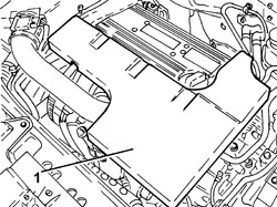
1. Remove the sound insulation cover fastened to the engine by three pins.
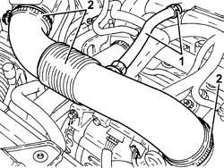
1. Loosen the band and disconnect the engine oil vapour recovery pipe from the cylinder head cover.
2. Loosen the bands and remove the air supply hose from the air flow meter to the throttle casing.
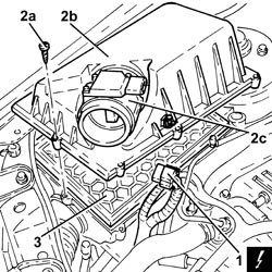
1. Disconnect the electrical connection from the air flow meter.
| Description | Connector | |
|---|---|---|
| 1 | Air flow meter | See K041 AIR FLOW METER |
2. Undo the bolts (2a) and remove the air filter cover (2b), complete with air flow meter (2c).
3. Remove the air cleaner filter element.
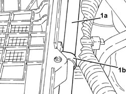
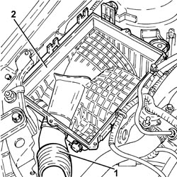
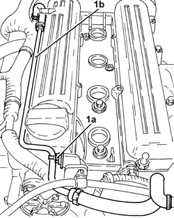
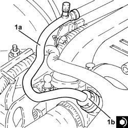
1. Release the fuel vapour pipe (1a) from the band (1b) on the air filter casing.
1. Disconnect the cold air intake from the air filter casing.
2. Remove the air filter casing fastened to the bodyshell by three pins.
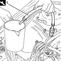
1. Connect the tool to the bleed valve on the fuel supply pipe and discharge the fuel pressure.
Follow the safety instructions and specific recommendations.
| Tool | Description | Function | Validity |
|---|---|---|---|
| 2000002900 | Breather connector | Fuel system pressure drainage | 1.8 2.2 |
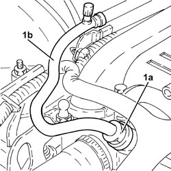
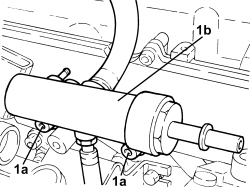
1. Undo the connector (1a), disconnect the fuel supply pipe (1b), fuel manifold pipe side and move it to the side.
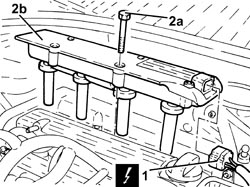
1. Disconnect the electrical connection from the ignition coil module.
| Description | Connector | |
|---|---|---|
| 1 | Ignition coil | See A030 IGNITION COIL |
2. Undo the bolts (2a) and remove the ignition coil module (2b).
1. Undo the nut (1a), loosen the bands and remove the engine coolant return pipe to the supply reservoir (1b).
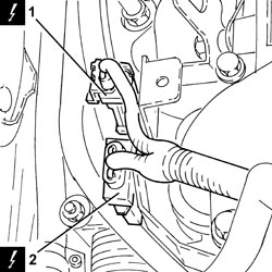
1. Disconnect the electrical connection for the front Lambda sensor to the catalytic converter.
| Description | Connector | |
|---|---|---|
| 1 | Lambda sensor on catalyzer | See K017 LAMBDA SENSOR ON CATALYZER |
2. Disconnect the electrical connection for the rear Lambda sensor to the catalytic converter.
| Description | Connector | |
|---|---|---|
| 2 | Lambda sensor on catalyzer - 2 | See K018 LAMBDA SENSOR ON CATALYZER - 2 |
1. Unscrew the bolts securing the timing side engine wiring brackets.
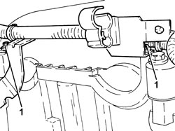
1. Unscrew the bolts securing the tappet cover side engine wiring brackets.
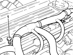
1. Release the gearbox side wiring mounting bracket from the fastenings.
2. Move the engine wiring to the side.
3. Disconnect the electrical connection for the radio interference condenser.
| Description | Connector | |
|---|---|---|
| 3 | Interference filter | See P087 NOISE FILTER |
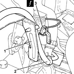
1. Undo the nut (1a) and disconnect the earth lead (1b) from the tappet cover.
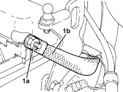
1. Undo the bolts (1a) and remove the tappet cover (1b).
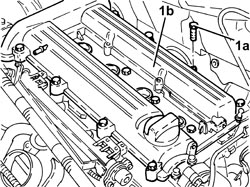
1. Disconnect the electrical connection from the air conditioning system multi-stage pressure switch.
| Description | Connector | |
|---|---|---|
| 1 | 4 stage pressure switch | See K010 4 STAGE PRESSURE SWITCH |
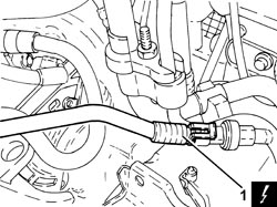
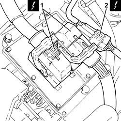
1. Disconnect the electrical connections from the injection/ignition system control unit.
| Description | Connector | |
|---|---|---|
| 1 | Engine management control unit | See M010 ENGINE MANAGEMENT CONTROL UNIT |
2. Disconnect the engine coupling.
| Description | Connector | |
|---|---|---|
| 2 | Engine coupling | See D029 ENGINE CABLES/ENGINE SERVICES CABLE COUPLING |
1. Tighten the bolts fixing the fuel manifold pipe.
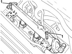
1. Release the fuel manifold pipe (1a) from its housing complete with injectors (1b) and remove it after having disconnected the electrical connections (1c) from the injectors.
| Description | Connector | |
|---|---|---|
| 1c | Injector | See N070 INJECTOR |
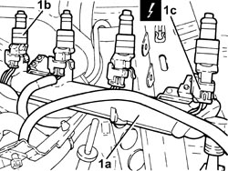
1. Disconnect the electrical connection from the throttle casing with D.V.L.
| Description | Connector | |
|---|---|---|
| 1 | Integrated throttle casing actuator | See N075 INTEGRATED THROTTLE CASING ACTUATOR |
2. Disconnect the electrical connection from the air pressure sensor.
| Description | Connector | |
|---|---|---|
| 2 | Absolute pressure sensor | See K048 ABSOLUTE PRESSURE SENSOR |
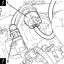
1. Undo the bolt (1a) and remove the engine oil dipstick tube (1b) assembly after having released it from the electrical wiring.
2. Undo the bolt fixing the electrical wiring mounting bracket to the air chamber.
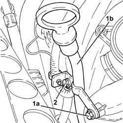
1. Loosen the band and disconnect the radiator lower coolant outlet hose, cylinder head side.
Collect the coolant that comes out in a suitable container.
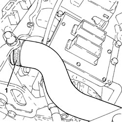
1. Disconnect the intermediate rapid connector for the fuel vapour pipe.
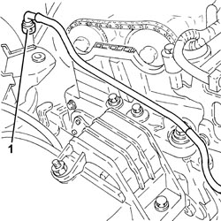
1. Disconnect the rapid connector for the fuel vapour recovery pipe, air chamber side.
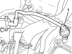
1. Disconnect the electrical connection from the fuel vapour recovery solenoid valve.
| Description | Connector | |
|---|---|---|
| 1 | Fuel vapour recovery solenoid valve | See L010 FUEL VAPOUR RECOVERY SOLENOID VALVE |
2. Release the fuel vapour recovery solenoid valve from the fastening, then remove it complete with pipes.
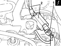
1. Disconnect the quick-release fitting for the brake servo vacuum intake pipe, air chamber side.
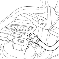
Op. 4450B04 RIGHT FRONT WHEEL - R.R
Op. 7055B66 ENGINE COMPARTMENT DUST COVER IN RIGHT FRONT WHEEL ARCH - R.R.
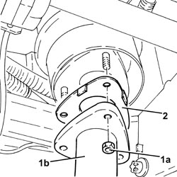
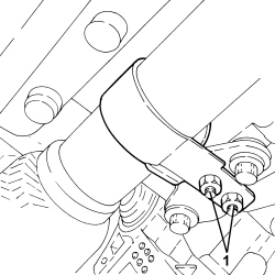
1. Undo the nuts (1a) and disconnect the front section of the exhaust pipe (1b), catalytic converter side.
Fasten the section of the exhaust pipe disconnected so that it is not hanging loose. The front section of the exhaust pipe including the flexible pipe can be fastened to the bodyshell appropriately using, for example metal wire.
Bends in the flexible pipe at angles of between 5° and 10°, starting from the planned fitting position, can damage the flexible pipe.
2. Remove the gasket.
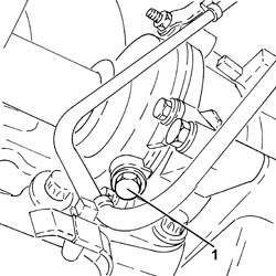
1. Undo the water pump coolant drain plug.
Collect the coolant that comes out in a suitable container.
Op. 7055B54 UNDER ENGINE PROTECTION/GUARD - R.R.
1. Undo the radiator coolant drain plug.
Collect the coolant in a suitable container.
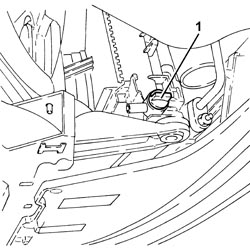
- Remove the spark plugs to facilitate the subsequent operations of rotating the engine.
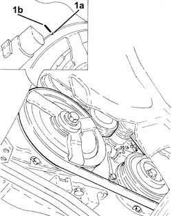
1. Rotate the crankshaft until cylinder no. 4 is at T.D.C. during the explosion stroke; in this condition the reference (1a) on the inner part of the crankshaft pulley should be aligned with the reference (1b) on the timing chain cover.
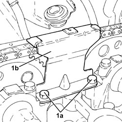
1. Undo the bolts (1a) and remove the timing chain upper plate (1b).
1. Undo the automatic timing chain tensioner and remove it.
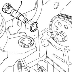
1. If there is no mark (1b) on the fixed timing hydraulic tensioner (1a), then the tensioner should be replaced with a new one, including a new tensioner moving plate.
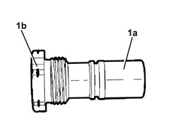
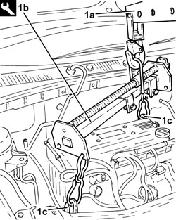
1. Support the power unit using a hydraulic hoist (1a) and the tool (1b) connected to the mounting brackets (1c).
| Tool | Description | Function | Validity |
|---|---|---|---|
| 1871001700 | Balance | Removing-refitting power unit |
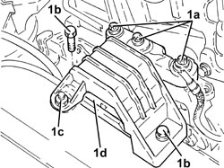
1. Undo the bolts (1a), (1b) and the nut (1c) and remove the flexible mounting for the timing side power unit front support (1d).
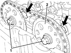
- Fasten the timing chain to the exhaust side camshaft toothed drive pulley using a band.
1. Loosen the bolts fixing the camshaft drive pulleys.
Apply counter-torque to the camshafts.
2. Remove the inlet side timing drive pulley.
1. Undo the access cap to the belt tensioner pad upper fixing bolt.
2. Undo the upper belt tensioner pad fixing bolt.
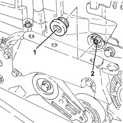
- Place the flexible mounting for the timing side power unit front support in its housing temporarily and secure it using the bolts and the nut.
- Remove the hydraulic hoist and tool used for supporting the power unit.
| Tool | Description | Function | Validity |
|---|---|---|---|
| 1871001700 | Balance | Removing-refitting power unit |
1. Undo and remove the front Lambda sensor on the catalytic converter.
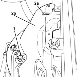
2. Undo the bolts (2a) and remove the heat shield (2b).
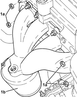
1. Undo the nuts (1a) and remove the exhaust manifold and catalytic converter (1b).
- Remove the gasket.
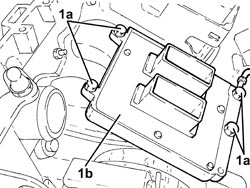
1. Undo the bolts (1a) and remove the injection/ignition system control unit (1b).
One of the bolts also secures the earth lead.
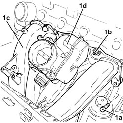
1. Undo the bolts (1a) and the nuts (1b) and remove the air chamber (1c) complete with throttle casing integrated with D.V.L. (1d).
- Remove the seals.
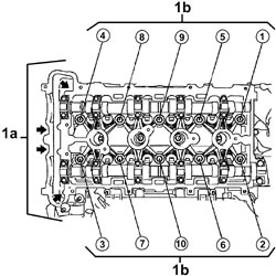
1. Undo the bolts (1a) and (1b) fixing the cylinder head to the engine block.
The bolts (1b) are loosened first by 1/4 turn, then 1/2 a turn in the order illustrated in the diagram.
- Remove the cylinder head.
Two mechanics are needed for this operation.
Take care to release the timing chain and the exhaust side camshaft drive pulley.
- Remove the cylinder head gasket.
Refitting
- Clean any residues of gasket from the the cylinder head - engine block matching surfaces.
- Carry out a visual inspection of the components:
- Check that the planarity of the lower cylinder head plane is within the recommended values, if this is not the case, replace the cylinder head (the cylinder head lower plane cannot be reground).
| Measurement | Value | Validity | ||
|---|---|---|---|---|
| Cylinder head lower surface flatness (mm) | 0.05 | 1.8 2.2 16V | ||
- Place the cylinder head gasket in position.
The gasket should be positioned with the word "TOP" facing upwards.
- Place the cylinder head in position.
Two mechanics are needed for this operation.
- Check that the centering bushes are correctly positioned.
Take care to raise the timing chain and the exhaust side camshaft drive pulley.
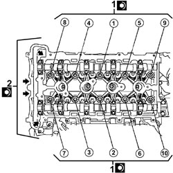
1. Tighten the new cylinder head fixing bolts to the recommended torque using the angular tightening tool.
Follow the order shown in the figure for each tightening sequence.
| Component | Fastening | dia | Value (daNm) | Validity |
|---|---|---|---|---|
| Cylinder head | Bolt (to be replaced) | M11 x 1.5 | (engine crankcase side) 3.0 + 90° +60° +15° | 2.2 |
| Tool | Description | Function | Validity |
|---|---|---|---|
| 1860942000 | Torque wrench | Tighten bolts to torque plus angle |
2. Tighten the new bolts securing the cylinder head to the recommended torque.
| Component | Fastening | dia | Value (daNm) | Validity |
|---|---|---|---|---|
| Cylinder head | Timing side bolts (to replace) | M8 X 1.25 | (engine crankcase side) 3.5 | 2.2 |
- Support the power unit using a hydraulic hoist and the tool connected to the mounting brackets.
| Tool | Description | Function | Validity |
|---|---|---|---|
| 1871001700 | Balance | Removing-refitting power unit |
- Tighten the bolts and the nut and remove the flexible mounting for the timing side power unit front support fitted temporarily.
1. Tighten the upper bolt fixing the belt tensioner pad to the recommended torque.
| Component | Fastening | dia | Value (daNm) | Validity |
|---|---|---|---|---|
| Timing fixed chain tensioner pad | Upper bolt | M6 x 1 | (cylinder head side) 0.8 | 2.2 |
2. Place the access cap for the belt tensioner pad upper in its housing and tighten the fixing bolt to the recommended torque.
Replace the seal.
| Component | Fastening | dia | Value (daNm) | Validity |
|---|---|---|---|---|
| Cap for timing fixed chain tensioner pad upper bolt | M22 x 1.5 | 6.5 | 2.2 |
- Remove the band used for fastening the timing chain to the exhaust side camshaft toothed drive pulley.
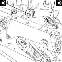
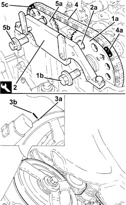
1. Place the inlet side camshaft toothed drive pulley (1a) in its housing and secure it without tightening the new bolt (1b).
2. Fit the camshaft timing tools.
Rotate the inlet side camshaft and insert the pin (2a) for the timing tool in the opening in the pulley.
| Tool | Description | Function | Validity |
|---|---|---|---|
| 2000000900 | Template | Camshaft timing adjustment | 2.2 |
3. If necessary, rotate the crankshaft until cylinder no. 4 is at T.D.C. during the explosion stroke; in this condition the reference (3a) on the inner part of the crankshaft pulley should be aligned with the reference (3b) on the timing chain cover.
Rotate the crankshaft slowly and evenly (in the direction of rotation of the engine).
Make sure that the timing chain is not stuck.
4. Fit the timing chain on the inlet side camshaft drive pulley.
The light blue mesh (4a) should be in line with the "INT" mark stamped on the inlet side camshaft drive pulley.
5. Place the exhaust side camshaft toothed drive pulley (5a) in its housing and secure it without tightening the new bolt (5b).
Rotate the exhaust side camshaft until the pink mesh (5c) is in line with the "EXH" mark on the exhaust side camshaft drive pulley.
- Retract the pin for the camshaft timing tool from the inlet side camshaft drive pulley.
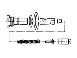
- The diagram illustrates the dismantling of the timing fixed hydraulic tensioner.
Replace the seals.
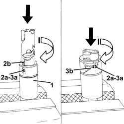
- Before it can be refitted the timing hydraulic tensioner must be pre-loaded as described below.
1. Place the piston in a vice fitted with protective jaws.
2. Insert the piston in the tensioner casing pressing it and rotating it as illustrated in the diagram until the pin (2a) is inserted in the notch (2b).
3. Press and, at the same time, rotate the piston until the pin (3a) engages in the groove (3b).
- Insert the piston assembled in this way in the tensioner casing.
1. Place the timing hydraulic tensioner in position and tighten it to the recommended torque.
| Component | Fastening | dia | Value (daNm) | Validity |
|---|---|---|---|---|
| Timing fixed hydraulic tensioner | M27 x 2 | 7.5 | 2.2 |
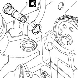
1. Hydraulic tensioner in operating position.
Place the timing hydraulic tensioner in the operating position exerting manual pressure on the chain in the area shown in the diagram. This tensions the chain which, acting on the moving plate, allows the release of the moving tensioner piston.
The operating spring is heard to make a "clack" noise when the tensioner piston is operated.
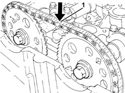
If the chain remains soft then the tensioner is not in the operating position.
- Rotate the crankshaft through 720°, then place cylinder no. 4 at T.D.C. during the explosion stroke; in this condition the reference on the inner part of the crankshaft pulley should be aligned with the reference on the timing chain cover.
When the crankshaft is rotated the tensioner piston should follow the chain during the rotation stage.
- Check the timing making sure that the tool pins coincide with the opening in the camshaft pullies.
If they are not aligned, fit the timing chain again no longer taking any notice of the coloured chain meshes as T.D.C. references.
- Remove the tool.
| Tool | Description | Function | Validity |
|---|---|---|---|
| 2000000900 | Template | Camshaft timing adjustment | 2.2 |
1. Place the timing chain upper plate (1a) in its housing and secure it tightening the bolts (1b) to the recommended torque.
| Component | Fastening | dia | Value (daNm) | Validity |
|---|---|---|---|---|
| Timing upper chain tensioner pad | Bolt (with thread-locking agent) | M6 x 1 | (cylinder head side) 1.0 | 2.2 |
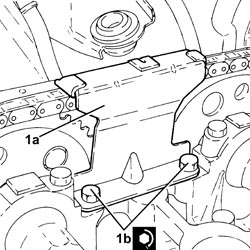
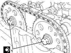
1. Tighten the new camshaft drive pulley fixing bolts to the recommended torque tightening the exhaust side pulley fixing bolt first.
Apply counter-torque to the camshafts.
| Component | Fastening | dia | Value (daNm) | Validity |
|---|---|---|---|---|
| Camshaft toothed drive pullies | Bolt (to be replaced) | M12 x 1.75 | (camshaft side) 8.5 + 30° + 15° | 2.2 |
- Fit the spark plugs and tighten them to the recommended torque.
| Component | Fastening | dia | Value (daNm) | Validity |
|---|---|---|---|---|
| Spark plugs | M14 x 1.25 | (cylinder head side) 2.2 | 2.2 |
1. Place the timing power unit front support flexible mounting (1a) in its housing and secure it tightening the bolts (1b) and (1c) and the nut (1d) to the recommended torque.
| Component | Fastening | dia | Value (daNm) | Validity |
|---|---|---|---|---|
| Timing side power unit rigid support flexible mounting | Bolt | M10 | (rigid support side) 5.0 - 6.0 | 1.8 2.2 1.9 JTD 16v 1.9 JTD 8v |
| Component | Fastening | dia | Value (daNm) | Validity |
|---|---|---|---|---|
| Timing side power unit rigid support flexible mounting | Bolt | M10 | (bodyshell side) 5.0 - 6.0 |
| Component | Fastening | dia | Value (daNm) | Validity |
|---|---|---|---|---|
| Timing side power unit rigid support flexible mounting | Nut | M10 | (bodyshell side) 5.0 - 6.0 |
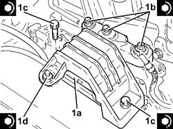
- Remove the hydraulic hoist and tool used for supporting the power unit.
| Tool | Description | Function | Validity |
|---|---|---|---|
| 1871001700 | Balance | Removing-refitting power unit |
- Clean the contact surfaces
- Place the new gaskets in their housings on the air chamber.
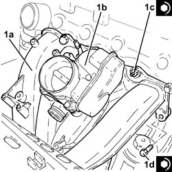
1. Refit the air chamber (1a) complete with throttle casing integrated with D.V.L. (1b) back in its housing and secure it tightening the nuts (1c) and the bolts (1d) to the recommended torque.
| Component | Fastening | dia | Value (daNm) | Validity |
|---|---|---|---|---|
| Air chamber | Nut | M6 x 1 | (cylinder head side) 0.9 | 2.2 |
| Component | Fastening | dia | Value (daNm) | Validity |
|---|---|---|---|---|
| Air chamber | Bolt | M6 x 1 | (cylinder head side) 0.9 | 2.2 |
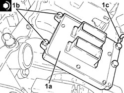
1. Place the injection/ignition system control unit (1a) in its housing and secure it tightening the bolts (1b) to the recommended torque.
One of the bolts also secures the earth lead (1c).
| Component | Fastening | dia | Value (daNm) | Validity |
|---|---|---|---|---|
| Injection/ignition system control unit | Bolt | M6 x 1 | (air chamber side) 0.9 | 2.2 |
- Place a new gasket back in position.
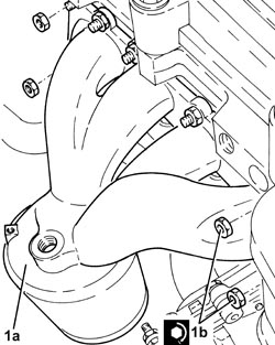
1. Place the exhaust manifold (1a) in its housing and secure it by tightening the new nuts (1b) to the recommended torque.
| Component | Fastening | dia | Value (daNm) | Validity |
|---|---|---|---|---|
| Exhaust manifold with catalytic converter | Nut (to replace) | (cylinder head side) 2.0 | 1.8 2.2 |
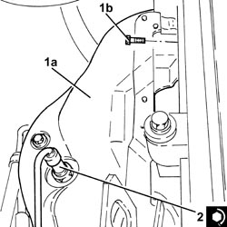
1. Place the heat shield (1a) in its housing and secure it using the bolts (1b).
2. Position the front Lambda sensor in its housing and tighten it to the recommended torque.
| Component | Fastening | dia | Value (daNm) | Validity |
|---|---|---|---|---|
| Front Lambda sensor to catalytic converter | - (with special black grease) | M18 x 1.5 | (exhaust manifold with catalytic converter side) 4.0 | 2.2 |
- Tighten the radiator coolant drain plug.
Op. 7055B54 UNDER ENGINE PROTECTION/GUARD - R.R.
- Remove the hydraulic hoist and tool used for supporting the power unit safely.
| Tool | Description | Function | Validity |
|---|---|---|---|
| 1871001700 | Balance | Removing-refitting power unit |
1. Tighten the coolant drain plug to the water pump to the recommended torque.
Apply sealant to the plug before fitting it.
| Component | Fastening | dia | Value (daNm) | Validity |
|---|---|---|---|---|
| Drain plug on water pump | M20 x 1.5 | (water pump side) 2.0 | 2.2 |
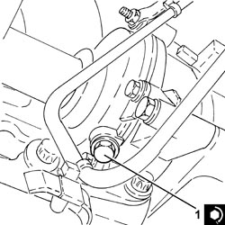
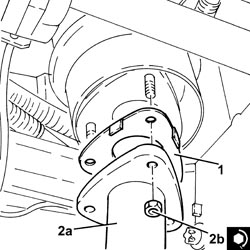
1. Place a new gasket in position.
2. Connect the front section of the exhaust pipe (2a), exhaust manifold side with the catalytic converter and tighten the new nuts (2b) to the recommended torque.
| Component | Fastening | dia | Value (daNm) | Validity |
|---|---|---|---|---|
| Rigid pipe for exhaust pipe between catalytic converter and silencer | Nut (to replace) | M8 | (exhaust manifold with catalytic converter side) 1.6 | 2.2 |
Op. 7055B66 ENGINE COMPARTMENT DUST COVER IN RIGHT FRONT WHEEL ARCH - R.R.
Op. 4450B04 RIGHT FRONT WHEEL - R.R
- Connect the quick-release fitting for the brake servo vacuum intake pipe, air chamber side.
- Place the fuel vapour recovery solenoid valve complete with pipes in its housing and secure it.
- Connect the electrical connection to the fuel vapour recovery solenoid valve.
- Connect the rapid connector for the fuel vapour recovery pipe, air chamber side.
- Connect the intermediate rapid connector for the fuel vapour pipe.
- Connect the radiator lower coolant inlet hose, cylinder head side, and tighten the band.
- Tighten the bolt fixing the electrical wiring mounting bracket to the air chamber.
- Place the engine oil dipstick pipe back in its housing and fasten it with the bolt.
- Secure the electrical wiring to the fastenings on the engine oil dipstick tube.
- Connect the electrical connection to the air pressure sensor.
- Connect the electrical connection to the throttle casing with D.V.L.
- Connect the electrical connections to the injectors, then place the fuel manifold pipe, complete with injectors, in its housing.
- Tighten the bolts fixing the fuel manifold pipe to the recommended torque.
| Component | Fastening | dia | Value (daNm) | Validity |
|---|---|---|---|---|
| Fuel manifold pipe | Bolt | M6 x 1 | (cylinder head side) 0.9 | 2.2 |
- Connect the engine coupling.
- Connect the electrical connections to the injection/ignition system control unit.
- Connect the electrical connection to the air conditioning system multi-stage pressure switch.
1. Place the tappet cover (1a) in its housing and secure it tightening the bolts (1b) to the recommended torque.
Replace the seals (1c).
| Component | Fastening | dia | Value (daNm) | Validity |
|---|---|---|---|---|
| Tappet cover | Bolt | M6 x 1 | (cylinder head side) 0.9 | 2.2 |
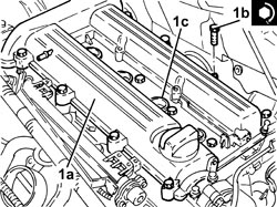
- Connect the earth loom to the tappet cover and secure it using the nut.
- Connect the electrical connection for the radio interference condenser.
- Refit the engine wiring
- Fasten the gearbox side engine wiring mounting bracket.
- Fasten the bolts securing the tappet cover side engine wiring brackets.
- Fasten the timing side engine wiring brackets using the bolts.
- Connect the electrical connection for the rear Lambda sensor to the catalytic converter.
- Connect the electrical connection for the front Lambda sensor to the catalytic converter.
- Place the coolant return pipe to the engine coolant reservoir in position and tighten the bands and the nut.
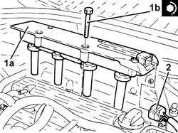
1. Place the ignition coil module (1a) in its housing and secure it tightening the bolts (1b) to the recommended torque.
| Component | Fastening | dia | Value (daNm) | Validity |
|---|---|---|---|---|
| Ignition coil module | Bolt | M6 x 1 | (tappet cover side) 0.9 | 2.2 |
2. Connect the electrical connection to the ignition coil module.
1. Place the fuel supply pipe (1a) in its housing, connect it and tighten the connector (1b) to the recommended torque.
| Component | Fastening | dia | Value (daNm) | Validity |
|---|---|---|---|---|
| Front fuel supply pipe | Connector | (fuel manifold side) 1.0 | 2.2 |
- Place the air filter casing in its housing and secure it to the bodyshell using the three pins.
- Connect the cold air intake to the air filter casing.
- Fasten the fuel vapour pipe to the air filter casing using the band.
- Fit the air filter filter element in place.
- Fit the cover for the air filter, complete with air flow meter, and secure it using the bolts.
- Connect the electrical connection to the air flow meter.
- Place the air supply hose from the air flow meter to the throttle casing back in its housing and secure it using the bands.
- Connect the engine oil vapour recovery pipe to the cylinder head cover and secure it using the band.
- Place the sound insulation cover back in its housing and secure it to the engine using the three pins.
- Connect the negative battery terminal.
Op. 0010T20 ENGINE COOLANT - CHANGE
- Remove the vehicle from the lift.
Removing
- Position the vehicle on a lift.
Op. 1016A10 SOUND-PROOFING COVER - R.R
Op. 5530B52 BATTERY SUPPORT/DRIP TRAY - R.R
Op. 1084A16 OIL DIPSTICK PIPE - R.R
Op. 1048A50 TURBOCHARGER AIR INTAKE PIPE - R.R.
Op. 4450B12 FRONT WHEELS (TWO) - R+R
Op. 7055B66 ENGINE COMPARTMENT DUST COVER IN RIGHT FRONT WHEEL ARCH - R.R.
Op. 7055B91 RIGHT FRONT WHEEL ARCH LINER - R.R.
Op. 7055B54 UNDER ENGINE PROTECTION/GUARD - R.R.
1. Undo the radiator coolant drain plug.
Collect the coolant in a suitable container.
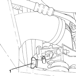
1. Disconnect the rapid connector for the fuel return pipe to the tank, fuel return manifold side.
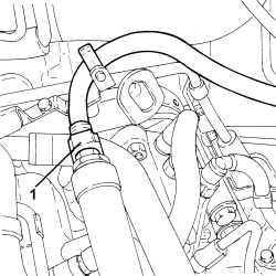
1. Disconnect the vacuum intake pipes from the vacuum reservoir.
2. Loosen the bands and disconnect the engine oil vapour recovery pipes, engine oil vapour separator side.
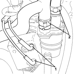
1. Undo the bolts (1a) and remove the oil vapour recovery pipe between the separator and the turbo (1b).
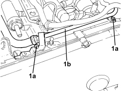
1. Disconnect the flexible pipe from the rigid vacuum intake pipe from the vacuum pump.
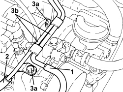
2. Disconnect the flexible pipe from the rigid vacuum intake pipe for the turbocharger vane position actuator control solenoid.
3. Undo the bolts (3a) and remove the vacuum pipes (3b).
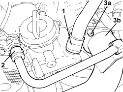
1. Loosen the band and disconnect the engine oil vapour recovery pipe, engine oil filler side.
2. Disconnect the rapid connector for the vacuum intake pipe from the vacuum pump.
3. Undo the bolts (3a) and disconnect the air supply hose from the heat exchanger to the intake manifold (3b), throttle body side.
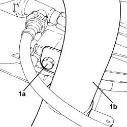
1. Undo the bolt (1a) and move the air supply hose from the heat exchanger to the intake manifold (1b) to the side.
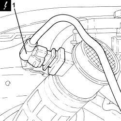
1. Disconnect the electrical connection from the air flow meter.
| Description | Connector | |
|---|---|---|
| 1 | Air flow meter | See K041 AIR FLOW METER |
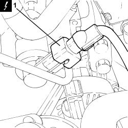
1. Disconnect the electrical connection for the fuel pressure regulator.
| Description | Connector | |
|---|---|---|
| 1 | Fuel pressure regulator | See N077 FUEL PRESSURE REGULATOR |
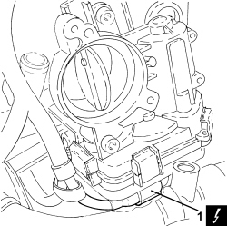
1. Disconnect the electrical connection from the throttle casing.
| Description | Connector | |
|---|---|---|
| 1 | Integrated throttle casing actuator | See N075 INTEGRATED THROTTLE CASING ACTUATOR |
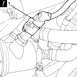
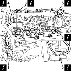
1. Disconnect the electrical connection from the engine coolant temperature sensor.
| Description | Connector | |
|---|---|---|
| 1 | Engine coolant temperature sensor/sender unit | See K036 ENGINE COOLANT TEMPERATURE SENSOR/SENDER UNIT |
1. Disconnect the electrical connection from the cam angle sensor.
| Description | Connector | |
|---|---|---|
| 1 | Timing sensor | See K047 TIMING SENSOR |
2. Disconnect the electrical connection of the air conditioner compressor.
| Description | Connector | |
|---|---|---|
| 2 | Air conditioning compressor engagement electro-magnet | See L020 AIR CONDITIONING COMPRESSOR ENGAGEMENT ELECTRO-MAGNET |
3. Disconnect the electrical connections from the injectors.
| Description | Connector | |
|---|---|---|
| 3 | Injector | See N070 INJECTOR |
4. Disconnect the electrical connection from the fuel pressure regulator on the injector single manifold.
| Description | Connector | |
|---|---|---|
| 4 | Fuel pressure regulator on rail | See N087 FUEL PRESSURE REGULATOR ON RAIL |
5. Disconnect the electrical connection from the fuel pressure sensor.
| Description | Connector | |
|---|---|---|
| 5 | Fuel pressure sensor | See K083 FUEL PRESSURE SENSOR |
6. Disconnect the electrical connections from the heater plugs.
| Description | Connector | |
|---|---|---|
| 6 | Heater plugs | See A040 HEATER PLUGS |
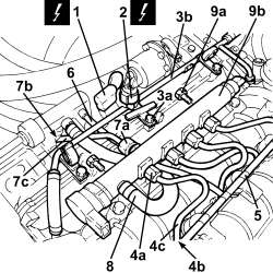
1. Disconnect the electrical connection for the pressure relief sensor.
| Description | Connector | |
|---|---|---|
| 1 | Air pressure - temperature sensor | See K044 AIR PRESSURE - TEMPERATURE SENSOR |
2. Disconnect the electrical connection from the EGR system solenoid valve
| Description | Connector | |
|---|---|---|
| 2 | EGR solenoid valve | See L030 EGR SOLENOID VALVE |
3. Loosen the bands, undo the bolts (3a) and remove the coolant return pipe to the engine coolant reservoir (3b).
4. Unscrew the connectors (4a) and (4b) and remove the pipes from the fuel manifold to the injectors (4c).
5. Manually push the clips and disconnect the pipe from the injectors to the fuel recovery manifold, injector side.
6. Disconnect the pipe from the injectors to the fuel recovery manifold, fuel recovery manifold side and remove it.
7. Undo the connectors (7a), (7b) and remove the pipe from the pressure pump to the fuel manifold (7c).
8. Loosen the bands and remove the fuel return pipe from the fuel manifold to the fuel return manifold.
9. Undo the fixing bolts (9a) and remove the single fuel manifold pipe (9b).
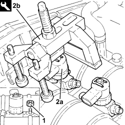
1. Undo the injector bracket retaining nuts.
2. Remove the injectors (2a) complete with brackets using the tools (2b).
If the injectors are being reused, mark the cylinder to which they belong so that they can be correctly refitted.
If a new injector/new inectors are fitted:
- determine the identification code stamped on the top surface;
- check, using an Examiner, the the new injector(s) is (are) recognized by the engine management control unit.
Start the removal beginning with the injector for cylinder no. 1 and continue with the injectors for cylinders 2, 3, 4 and 5.
| Tool | Description | Function | Validity |
|---|---|---|---|
| 1870897300 | Extractor | Removing injectors | 1.9 JTD 8V 1.9 JTD 16V 2.4 JTD 20V |
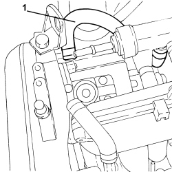
1. Loosen the band and disconnect the fuel return pipe from the pressure pump to the fuel return manifold, pressure pump side.
1. Undo the bolts (1a) and remove the fuel return manifold (1b) with pipes.
Op. 1088D14 UPPER RADIATOR COOLANT OUTLET HOSE - R.R.
1. Loosen the bands and disconnect the pipes from the water pump rigid inlet pipe.
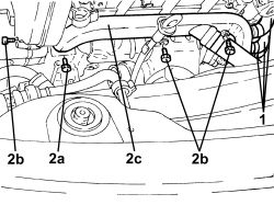
2. Undo the bolts (2a), (2b) and remove the water pump rigid inlet pipe (2c).
- Remove the gasket.
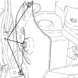
1. Undo the lower nuts fixing the exhaust manifold heat shield.
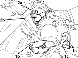
1. Undo the bolts (1a), (1b) and remove the catalytic converter mounting bracket (1c).
2. Undo the bolts (2a) securing the engine oil return pipe from the turbocharger (2b), crankcase sump side.
1. Undo the nuts fixing the intermediate exhaust pipe mounting bracket.
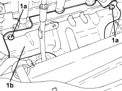
1. Undo the upper bolts (1a) and remove the exhaust manifold heat shield (1b).
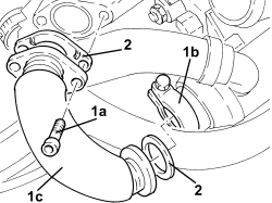
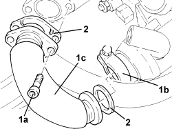
1. Undo the bolts (1a), loosen the collar (1b) and remove the E.G.R. system exhaust gas/water heat exchanger exhaust gas inlet pipe (1c).
2. Remove the seal.
1. Undo the nuts (1a) and move the turbocharger (1b) complete with catalytic converter and exhaust pipe and secure them appropriately.
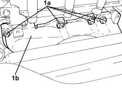
1. Undo the bolts (1a) and remove the engine oil filler (1b).
2. Remove the gasket.
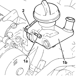
1. Undo the bolts (1a) and remove the vacuum unit (1b).
2. Remove the gasket.
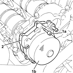
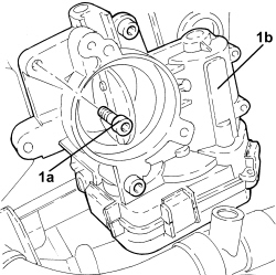
1. Undo the bolts (1a) and remove the throttle body (1b).
- Remove the gasket.
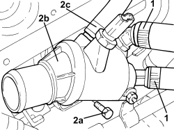
1. Loosen the bands and disconnect the pipes from the thermostat.
2. Undo the nut fixing the engine coolant return pipe from the engine oil heat exchanger.
3. Undo the bolts (3a) and remove the thermostat (3b) complete with O-ring.
1. Undo the bolts fixing the exhaust gas outlet from the water/exhaust gas heat exchanger for the E.G.R. system, E.G.R. solenoid valve side.
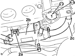
2. Undo the bolts (2a) and remove the water/exhaust gas heat exchanger for the E.G.R. system (2b) complete with exhaust gas outlet pipe (2c).
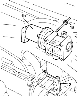
1. Undo the fixing bolts (1a) and remove the E.G.R. system solenoid valve (1b).
2. Remove the gasket.
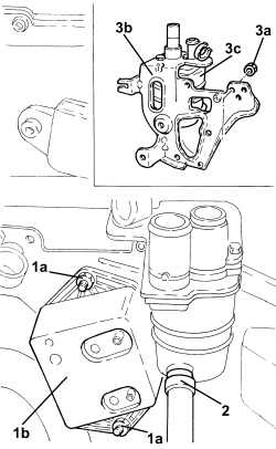
1. Undo the nuts (1a) and remove the vacuum reservoir (1b).
2. Loosen the band and disconnect the condensed engine oil recovery pipe, engine oil vapour separator side.
3. Undo the fastenings (3a) and remove the bracket (3b) complete with engine oil vapour separator (3c).
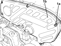
1. Undo the bolts (1a) and remove the protective timing cover (1b).
Op. 4410D16 BRACKET (ONE) RETAINING CHASSIS TO BODY - R R
Op. 1092G10 SINGLE ENGINE BELT - R.R
Op. 1092A10 CRANKSHAFT PULLEY - R + R
- Position a hydraulic jack beneath the engine.
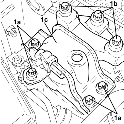
1. Undo the bolts (1a), (1b), then remove the power unit timing side front support flexible mounting (1c).
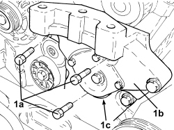
1. Undo the bolts (1a) and remove the power unit timing side rigid support (1b) complete with fixed tensioner (1c).
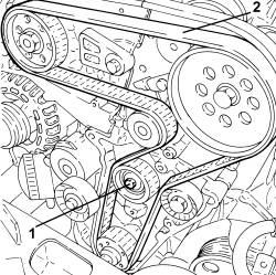
1. Loosen the bolt retaining the timing belt moving tensioner.
2. Release and remove the toothed timing drive belt.
- Fit the timing side power unit rigid support temporarily in its housing and secure it using the bolts.
- Fit the timing side power unit front support flexible mounting temporarily in its housing and secure it using the bolts.
- Remove the hydraulic jack from beneath the engine.
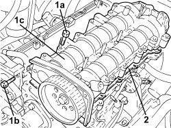
1. Undo the bolts (1a) and (1b) and remove the camshaft housing assembly (1c).
2. Remove the gasket.
1. Remove the hydraulic tappets.
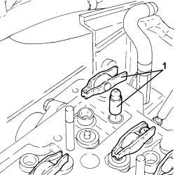
1. Disconnect the electrical connection from the throttle control shaft valve for the inlet ducts.
| Description | Connector | |
|---|---|---|
| 1 | Flow modifier solenoid valve | See L064 FLOW MODIFYING SOLENOID VALVE |
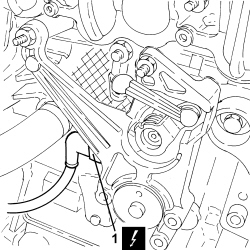
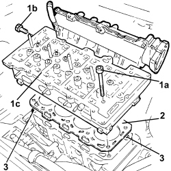
1. Undo the bolts (1a) and (1b) and remove the lower cylinder head assembly (1c).
2. Remove the cylinder head gasket.
3. Remove the locating bushes.
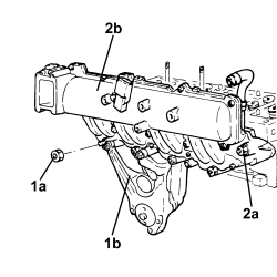
- Disconnect the linkage for the throttle control shaft valve for the inlet ducts.
1. Working at the bench, undo the nuts (1a) and remove the throttle control shaft valve for the inlet ducts (1b).
2. Undo the nuts (2a) and remove the air chamber (2b) complete with gasket.
Refitting
- Clean any residues of the old gasket from the lower cylinder head plane.
- Check that the flatness of the lower cylinder head plane corresponds to the recommended values.
| Measurement | Value | Validity | ||
|---|---|---|---|---|
| Cylinder head lower surface flatness (mm) | 0.1 ± 0.05 | 1.9 JTD 16V | ||
1. If the planarity of the lower cylinder head plane does not correspond to the recommended figures, regrind it without exceeding the minimum permitted height.
| Measurement | Value | Validity | ||
|---|---|---|---|---|
| Minimum permitted cylinder head height (mm) | 107.00 ± 0.05 | 1.9 JTD 16V | ||
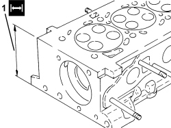
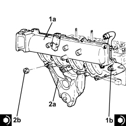
1. Fit the air chamber (1a) complete with gasket back in its housing and secure it tightening the nuts (2b) to the recommended torque.
| Component | Fastening | dia | Value (daNm) | Validity |
|---|---|---|---|---|
| Intake manifold | Nut | M8 | (cylinder head side) 2.3 - 2.8 | 1.9 JTD 16v |
2. Place the throttle control shaft valve for the inlet ducts (2a) back in its housing and secure it tightening the nuts (2b) to the recommended torque.
| Component | Fastening | dia | Value (daNm) | Validity |
|---|---|---|---|---|
| Throttle carrier shaft control valve for inlet ducts | Nut | M6 | 0.65 ÷ 0.75 | 1.9 JTD 16v 2.4 JTD 20v |
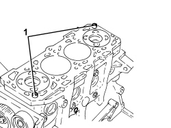
1. Position the cylinder head locating bushes on the crankcase as shown in the figure.
The locating bushes between the crankcase and cylinder head are shorter (12.5 mm) than the bushes between the cylinder head and the cylinder head extension. Take gret care not to reverse them as this could impair engine operation.
- Fit a new cylinder head gasket in position.
If the cylinder head has to be refaced, use a new cylinder head gasket that is the same size as the one removed. If, on the other hand, the cylinder head has had to be refaced, the size of the new cylinder head gasket to be used must be determined (see operation 1004E20).
Position the first cylinder at T.D.C.; rotate the crankshaft a further two teeth of the toothed timing drive pulley to lower the pistons thereby preventing any interference with the valves whilst fitting the cylinder head.
- Position the cylinder head on the cylinder block/crankcase.
Do not reuse the cylinder head bolts more than four times because they undergo permanent lengthening whenever they are tightened.
Replace the bolts if the number of times that the bolts have been tightenened to the cylinder head is unknown.
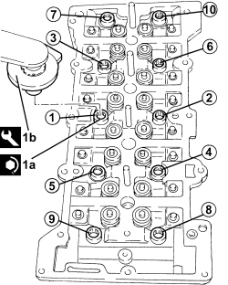
1. Tighten the cylinder head bolts (1a) to the recommended torque using the angular tightening tool (1b).
| Component | Fastening | dia | Value (daNm) | Validity |
|---|---|---|---|---|
| Cylinder head | Bolt | M12 | (engine crankcase side) 6.2 - 6.8 + 90° + 90° + 90° | 1.9 JTD 16v |
| Tool | Description | Function | Validity |
|---|---|---|---|
| 1860942000 | Torque wrench | Tighten bolts to torque plus angle |
Follow the order shown in the figure for each tightening sequence.
- Connect the electrical connection to the throttle control shaft valve for the inlet ducts.
- Place the hydraulic tappets in their housings.
1. Position the camshaft housing centering bushes on the cylinder head as illustrated in the diagram.
The centering bushes between the cylinder head and the camshaft housing are longer (16.0) than those between the engine block and the cylinder head; take care therefore not to mix them up because this could adversely affect the operation of the engine.
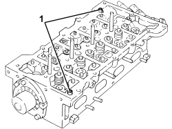
- Place the camshaft housing gasket in position.
1. Position the camshaft housing assembly (1a) in its housing and secure it by tightening the bolt (1b) and the new bolts (1c) to the recommended torque.
| Component | Fastening | dia | Value (daNm) | Validity |
|---|---|---|---|---|
| Camshaft housing | Bolt | M8 | (cylinder head side) 2.3 - 2.8 | 1.9 JTD 16v |
| Component | Fastening | dia | Value (daNm) | Validity |
|---|---|---|---|---|
| Pressure pump mounting | Bolt (pretreated to be replaced) | M8 | (cylinder head extension side) 2.3 - 2.8 | 1.9 JTD 16v |
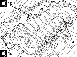
- Position a hydraulic jack beneath the engine.
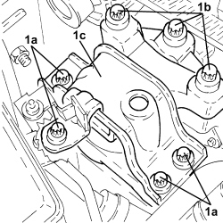
1. Undo the bolts (1a), (1b), then remove the power unit timing side front support flexible mounting (1c) fitted temporarily.
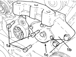
1. Undo the bolts (1a) and remove the power unit timing side rigid support (1b) complete with fixed tensioner (1c) fitted temporarily.
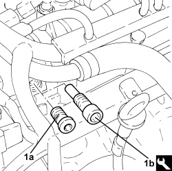
1. Remove the plug (1a) and refit the exhaust camshaft template (1b).
| Tool | Description | Function | Validity |
|---|---|---|---|
| 1870896900 | Template | Engine tuning | 1.9 JTD 16V |
nly fit the exhaust side camshaft template because the intake side template seat is not accessible.
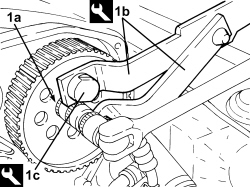
1. Loosen the bolt (1a) fixing the exhaust side camshaft toohted pulley using tools (1b) and (1c) for counter-torque.
| Tool | Description | Function | Validity |
|---|---|---|---|
| 1870815000 | Counter-torque | Loosen/tighten timing driven toothed pulley fixing bolt Loosen/tighten nut securing front driveshaft to wheel hub | 1.9 JTD 16V 1.9 JTD 8V |
| Tool | Description | Function | Validity |
|---|---|---|---|
| 1870836000 | Pins | Loosen/tighten timing driven toothed pulley fixing bolt | 1.9 JTD 16V 1.9 JTD 8V |
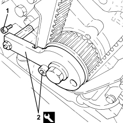
1. Undo the bolt fixing the crankcase front cover shown in the diagram.
- Temporarily fit the toothed timing drive belt on the toothed drive pulley.
2. Fit the tool and fasten it using the calibrated screw.
The crankshaft must be rotated, using small movements, to allow the locating dowel on the timing drive pulley to be inserted in the opening in the tool.
| Tool | Description | Function | Validity |
|---|---|---|---|
| 2000003000 | Template | Engine tuning | 1.9 JTD 16V 1.9 JTD 8V |
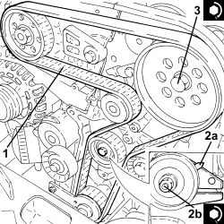
1. Fit the toothed timing belt completely taking care to ensure that the yellow references on it are aligned with the references on the toothed pullies.
2. Use a screwdriver for leverage on the tensioner arm until the reference (2a) for the tensioner is in the maximum tension position and tighten the tensioner bolts (2b) to the recommended torque in this position.
| Component | Fastening | dia | Value (daNm) | Validity |
|---|---|---|---|---|
| Timing moving tensioner | Nut | M8 | 2.3 ÷ 2.8 | 1.9 JTD 16v 1.9 JTD 8v |
3. Tighten the bolt fixing the exhaust side camshaft toothed pulley to the recommended torque using the tool for counter-torque.
| Component | Fastening | dia | Value (daNm) | Validity |
|---|---|---|---|---|
| Driven toothed pulley | Bolt | M12 | (camshaft side) 2.9 - 3.2 + 40° | 1.9 JTD 16v 1.9 JTD 8v |
| Tool | Description | Function | Validity |
|---|---|---|---|
| 1870815000 | Counter-torque | Loosen/tighten timing driven toothed pulley fixing bolt Loosen/tighten nut securing front driveshaft to wheel hub | 1.9 JTD 16V 1.9 JTD 8V |
| Tool | Description | Function | Validity |
|---|---|---|---|
| 1870836000 | Pins | Loosen/tighten timing driven toothed pulley fixing bolt | 1.9 JTD 16V 1.9 JTD 8V |
- Remove the timing tools.
| Tool | Description | Function | Validity |
|---|---|---|---|
| 1870896900 | Template | Engine tuning | 1.9 JTD 16V |
Remove the exhaust camshaft side template because the intake side camshaft has not been fitted.
| Tool | Description | Function | Validity |
|---|---|---|---|
| 2000003000 | Template | Engine tuning | 1.9 JTD 16V 1.9 JTD 8V |
- Rotate the crankshaft through two revolutions.
1. Loosen the moving timing tensioner nut.
2. Use a screwdriver for leverage on the tensioner arm until the reference (2a) for the tensioner is in line with the reference opening (2b) and tighten the tensioner bolt (2c) to the recommended torque in this position.
| Component | Fastening | dia | Value (daNm) | Validity |
|---|---|---|---|---|
| Timing moving tensioner | Nut | M8 | 2.3 ÷ 2.8 | 1.9 JTD 16v 1.9 JTD 8v |
- Recheck the timing by refitting the timing tools.
nly fit the exhaust side camshaft template because the intake side template seat is not accessible.
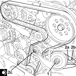
- Tighten the bolt fixing the crankcase front cover removed previously.
- Tighten the plug on the cylinder head extension for fitting the exhaust side timing tool.
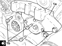
1. Place the power unit timing side rigid support (1a) in its housing and secure it tightening the bolts (1b) to the recommended torque.
| Component | Fastening | dia | Value (daNm) | Validity |
|---|---|---|---|---|
| Timing side power unit rigid support | Bolt | M10 | (engine crankcase side) 4.5 - 5.5 | 1.9 JTD 8v 1.9 JTD 16v |
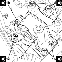
1. Place the timing side power unit front support flexible mounting (1a) in its housing and secure it tightening the bolts (1b), (1c) and (1d) to the recommended torque.
| Component | Fastening | dia | Value (daNm) | Validity |
|---|---|---|---|---|
| Timing side power unit rigid support flexible mounting | Bolt | M10 | (bodyshell side) 5.0 - 6.0 |
| Component | Fastening | dia | Value (daNm) | Validity |
|---|---|---|---|---|
| Timing side power unit rigid support flexible mounting | Nut | M10 | (bodyshell side) 5.0 - 6.0 |
| Component | Fastening | dia | Value (daNm) | Validity |
|---|---|---|---|---|
| Timing side power unit rigid support flexible mounting | Bolt | M10 | (rigid support side) 5.0 - 6.0 | 1.8 2.2 1.9 JTD 16v 1.9 JTD 8v |
- Remove the hydraulic jack under the engine crankcase sump.
- Remove the hydraulic jack from beneath the engine.
Op. 1092A10 CRANKSHAFT PULLEY - R + R
Op. 1092G10 SINGLE ENGINE BELT - R.R
Op. 4410D16 BRACKET (ONE) RETAINING CHASSIS TO BODY - R R
- Fit the timing belt covers and secure them using the bolts.
- Place the bracket complete with engine oil vapour separator in its housing and secure it.
- Connect the condensed oil recovery pipe, engine oil vapour separator side, and tighten the band.
- Place the vacuum reservoir back in its housing and secure it using the nuts.
1. Place the gasket back in its housing.
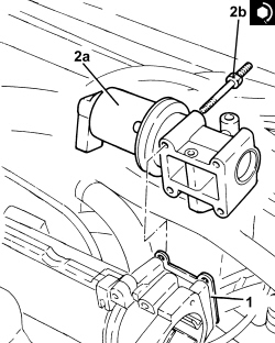
2. Place the E.G.R. system solenoid valve (2a) in its housing and fasten it tightening the bolts (2b) to the recommended torque.
| Component | Fastening | dia | Value (daNm) | Validity |
|---|---|---|---|---|
| E.G.R. system solenoid valve | Bolt | M6 | (chamber side) 2.5 | 1.9 JTD 16v 2.4 JTD 20v |
1. Replace the E.G.R. system exhaust gas/water heat exchanger (1a) back in its housing complete with exhaust gas outlet pipe (1b) and secure by tightening the bolts (1c) to the specified torque.
| Component | Fastening | dia | Value (daNm) | Validity |
|---|---|---|---|---|
| Exhaust gas/water heat exchanger for E.G.R. system | Bolt | M8 | (cylinder head side) 2.3 - 2.8 | 1.9 JTD 16v 1.9 JTD 8v 2.4 JTD 20v |
2. Tighten the bolts fixing the exhaust gas outlet from the water/exhaust gas heat exchanger for the E.G.R. system, E.G.R. solenoid valve side to the recommended torque.
| Component | Fastening | dia | Value (daNm) | Validity |
|---|---|---|---|---|
| Exhaust gas/water heat exchanger for E.G.R. system | Bolt | M8 | (EGR solenoid side) 2.3 - 2.8 | 1.9 JTD 16v 1.9 JTD 8v 2.4 JTD 20v |
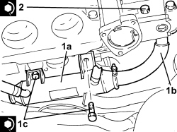
1. Place the thermostat (1a) in its housing with the O-ring and secure it by tightening the bolts (1b) to the recommended torque.
| Component | Fastening | dia | Value (daNm) | Validity |
|---|---|---|---|---|
| Thermostat | Bolt | M8 | (cylinder head side) 2.5 | 1.9 JTD 16v 2.4 JTD 20v |
2. Tighten the nut fixing the engine coolant return pipe from the engine oil heat exchanger.
3. Connect the pipes to the thermostat and tighten the bands.
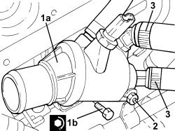
- Place the gasket back in its housing.
1. Place the throttle body (1a) in its housing and secure it tightening the bolts (1b) to the recommended torque.
| Component | Fastening | dia | Value (daNm) | Validity |
|---|---|---|---|---|
| Throttle body | Bolt | (chamber side) 2.5 | 1.9 JTD 16v 2.4 JTD 20v |
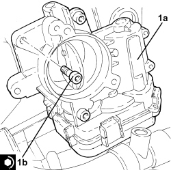
1. Place the gasket back in its housing.
2. Place the vacuum unit (2a) in its housing and secure it by tightening the new bolts (2b) to the recommended torque.
| Component | Fastening | dia | Value (daNm) | Validity |
|---|---|---|---|---|
| Vacuum unit | Bolt (pretreated to be replaced) | M6 | (cylinder head extension side) 0.5 + 50° | 1.9 JTD 16v 2.4 JTD 20v |
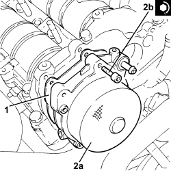
1. Place the gasket back in its housing.
2. Place the engine oil filler (2a) in its housing and secure it by tightening the bolts (2b) to the recommended torque.
| Component | Fastening | dia | Value (daNm) | Validity |
|---|---|---|---|---|
| Engine oil filler | Bolt | M6 | (cylinder head extension side) 0.8 - 1.0 | 1.9 JTD 16v 2.4 JTD 20v |
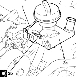
1. Place the turbocharger (1a) back in its housing complete with catalytic converter and intermediate exhaust pipe and tighten the nuts (1d) to the recommended torque.
| Component | Fastening | dia | Value (daNm) | Validity |
|---|---|---|---|---|
| Turbocharger and exhaust manifold assembly | Nut | M8 | (cylinder head side) 1.8 - 2.2 | 1.9 JTD 16v |
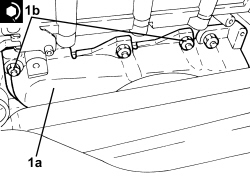
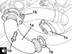
1. Place the E.G.R. system exhaust gas/water heat exchanger exhaust gas inlet pipe back in its housing complete with gaskets (1b), then fasten it using the collar (1c) and the bolts (1d) tightening them to the recommended torque.
| Component | Fastening | dia | Value (daNm) | Validity |
|---|---|---|---|---|
| Exhaust gas/water heat exchanger for E.G.R. system | Bolt | M8 | (exhaust manifold side) 2.3 - 2.8 | 1.9 JTD 16v 2.4 JTD 20v |
- Place the exhaust manifold heat shield back in its housing and secure it using the upper bolts.
- Tighten the nuts fixing the intermediate exhaust pipe mounting bracket.
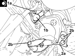
1. Tighten the bolts (1a) securing the engine oil return pipe from the turbocharger (1b), crankcase sump side to the recommended torque.
| Component | Fastening | dia | Value (daNm) | Validity |
|---|---|---|---|---|
| Engine oil supply pipe from turbocharger | Bolt | M8 | (engine crankcase side) 2.2 - 2.7 | 1.9 JTD 16v 1.9 JTD 8v |
2. Place the catalytic conveter mounting bracket (2a) in its housing and secure it using the bolts (2b).
- Tighten the lower nuts fixing the exhaust manifold heat shield.
1. Place the water pump rigid inlet pipe (1a), complete with gasket, in position and secure it tightening the bolts (1b) and (1c) to the recommended torque.
| Component | Fastening | dia | Value (daNm) | Validity |
|---|---|---|---|---|
| Water pump rigid inlet pipe | Bolt | M6 | (cylinder head side) 0.8 - 1.0 | 1.9 JTD 16v 1.9 JTD 8v |
2. Connect the pipes to the water pump rigid inlet pipe and tighten the bands.
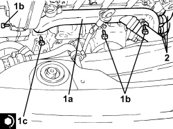
Op. 1088D14 UPPER RADIATOR COOLANT OUTLET HOSE - R.R.
- Place the fuel return manifold complete with pipes in its housing and secure it using the bolts.
- Connect the fuel return pipe from the pressure pump to the fuel return manifold, pressure pump side and tighten the band.
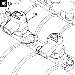
1. Refit the injectors (1a) complete with brackets and tighten nuts (1b) to the specified torque.
Start the refitting beginning with the injector for cylinder no. 4 and continue with the injectors for cylinders 3, 2, and 1.
| Component | Fastening | dia | Value (daNm) | Validity |
|---|---|---|---|---|
| Injector brackets | Nut | M8 | (cylinder head extension side) 2.3 - 2.8 | 1.9 JTD 16v 2.4 JTD 20v |
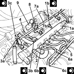
1. Place the single fuel manifold pipe (1a) in its housing and secure it tightening the bolts (1b) to the recommended torque.
| Component | Fastening | dia | Value (daNm) | Validity |
|---|---|---|---|---|
| Single fuel manifold pipe (rail) | Bolt | M8 | (cylinder head extension side) 2.3 - 2.8 | 1.9 JTD 16v 2.4 JTD 20v |
2. Place the fuel return pipe from the fuel manifold to the fuel return manifold in its housing and tighten the bands.
3. Place the pipe from the pressure pump to the fuel manifold pipe (3a) back in its housing and secure it tightening the connectors (3b) and (3c) to the recommended torque.
| Component | Fastening | dia | Value (daNm) | Validity |
|---|---|---|---|---|
| Pipe from pressure pump to fuel manifold | Connector | M14 | (fuel manifold side) 2.2 - 2.4 | 1.9 JTD 16v 2.4 JTD 20v |
| Component | Fastening | dia | Value (daNm) | Validity |
|---|---|---|---|---|
| Pipe from pressure pump to fuel manifold | Connector | M......... | (pressure pump side) ..................... | 1.9 JTD 16v 2.4 JTD 20v |
4. Fit the pipe from the injectors to the fuel recovery manifold and connect to the fuel recovery manifold.
5. Connect the pipe from the injectors to the fuel recovery manifold to the injectors and push home until the clips click into place.
6. Place the pipes from the fuel manifold to the injectors (6a) in their housings and secure them tightening the connectors (6b) and (6c) to the recommended torque.
| Component | Fastening | dia | Value (daNm) | Validity |
|---|---|---|---|---|
| Pipes from fuel manifold to injectors | Connector | M14 | (fuel manifold side) 2.2 - 2.4 | 1.9 JTD 16v 2.4 JTD 20v |
| Component | Fastening | dia | Value (daNm) | Validity |
|---|---|---|---|---|
| Pipes from fuel manifold to injectors | Connector | M12 | (injector side) 2.4 - 2.6 | 1.9 JTD 16v 2.4 JTD 20v |
7. Place the coolant return pipe to the engine coolant reservoir (7a) in position and secure it using the bolts (7b) and tighten the bands.
8. Connect the electrical connection to the E.G.R. system solenoid valve.
9. Connect the electrical connection for the pressure relief sensor.
- Connect the electrical connections to the heater plugs.
- Connect the electrical connection to the fuel pressure sensor.
- Connect the electrical connection to the fuel pressure regulator on the injector single manifold.
- Connect the electrical connections to the injectors.
- Connect the air conditioning compressor electrical connection.
- Connect the electrical connection to the cam angle sensor.
- Connect the electrical connection to the engine coolant temperature sensor.
- Connect the electrical connection to the throttle casing.
- Connect the electrical connection to the fuel pressure regulator.
- Connect the electrical connection to the air flow meter.
- Place the air supply pipe from the heat exchanger to the intake manifold back in its housing and secure it using the bolt.
- Connect the air supply hose from the heat exchanger to the intake manifold, throttle body side and secure it using the bolts.
- Connect the rapid connector for the vacuum intake pipe from the vacuum pump.
- Connect the engine oil vapour recovery pipe, engine oil filler side and tighten the band.
- Place the vacuum pipes in their housings and secure them using the bolts.
- Connect the flexible pipe to the rigid vacuum intake pipe for the turbocharger vane position actuator control solenoid.
- Connect the flexible pipe to the rigid vacuum intake pipe from the vacuum pump.
- Place the oil vaopur recovery pipe between the separator and the turbo in its housing and secure it using the bolts.
- Connect the engine oil vapour recovery pipes, engine oil vapour separator side and tighten the bands.
- Connect the vacuum intake pipes to the vacuum reservoir.
- Connect the rapid connector for the fuel return pipe to the tank, fuel return manifold side.
- Tighten the coolant drain plug to the radiator.
Op. 7055B91 RIGHT FRONT WHEEL ARCH LINER - R.R.
Op. 7055B66 ENGINE COMPARTMENT DUST COVER IN RIGHT FRONT WHEEL ARCH - R.R.
Op. 4450B12 FRONT WHEELS (TWO) - R+R
Op. 1048A50 TURBOCHARGER AIR INTAKE PIPE - R.R.
Op. 1084A16 OIL DIPSTICK PIPE - R.R
Op. 5530B52 BATTERY SUPPORT/DRIP TRAY - R.R
Op. 0010T20 ENGINE COOLANT - CHANGE
Op. 7055B54 UNDER ENGINE PROTECTION/GUARD - R.R.
Op. 1016A10 SOUND-PROOFING COVER - R.R
- Remove the vehicle from the lift.
Removing
- Position the vehicle on a lift.
Op. 1016A10 SOUND-PROOFING COVER - R.R
Op. 5530B52 BATTERY SUPPORT/DRIP TRAY - R.R
Op. 1048A10 AIR FILTER ASSEMBLY - R.R.
Op. 7055B54 UNDER ENGINE PROTECTION/GUARD - R.R.
Op. 4450B04 RIGHT FRONT WHEEL - R.R
Op. 7055B66 ENGINE COMPARTMENT DUST COVER IN RIGHT FRONT WHEEL ARCH - R.R.
Op. 7055B91 RIGHT FRONT WHEEL ARCH LINER - R.R.
Op. 1092G10 SINGLE ENGINE BELT - R.R
Op. 1092A10 CRANKSHAFT PULLEY - R + R
1. Undo the radiator coolant drain plug.
Collect the coolant in a suitable container.
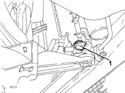
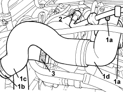
1. Unscrew bolts (1a), loosen collar (1b) and remove the sleeve (1c) and rigid air intake pipe (1d) to the throttle body.
2. Disconnect the rapid connector for the vacuum intake pipe from the vacuum pump.
3.Loosen the band and disconnect the upper coolant inlet hose to the radiator, thermostat side.
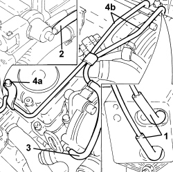
1. Disconnect the vacuum pipes from the vacuum reservoir.
2. Disconnect the vacuum pipe from the turbocharger vane position actuator control solenoid valve.
3. Disconnect the vacuum pipe from the vacuum pump.
4. Undo the fastenings (4a) and remove the vacuum pipes (4b).
1. Disconnect the electrical connection from the throttle casing.
| Description | Connector | |
|---|---|---|
| 1 | Integrated throttle casing actuator | See N075 INTEGRATED THROTTLE CASING ACTUATOR |
2. Disconnect the electrical connection from the fuel pressure sensor on the fuel manifold.
| Description | Connector | |
|---|---|---|
| 2 | Fuel pressure sensor | See K083 FUEL PRESSURE SENSOR |
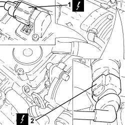
1. Disconnect the electrical connection from the engine coolant temperature sensor.
| Description | Connector | |
|---|---|---|
| 1 | Engine coolant temperature sensor/sender unit | See K036 ENGINE COOLANT TEMPERATURE SENSOR/SENDER UNIT |
2. Loosen the band and disconnect the coolant return pipe to the engine coolant reservoir, thermostat side.
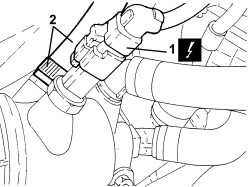
1. Loosen the bands (1a), undo the bolts (1b) and remove the coolant return pipe to the engine coolant reservoir (1c).
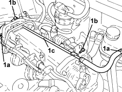
1. Disconnect the electrical connection from the EGR system solenoid valve
| Description | Connector | |
|---|---|---|
| 1 | E.G.R. solenoid valve | See L030 EGR SOLENOID VALVE |
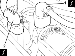
2. Disconnect the electrical connection for the pressure relief sensor.
| Description | Connector | |
|---|---|---|
| 2 | Air pressure - temperature sensor | See K044 AIR PRESSURE - TEMPERATURE SENSOR |
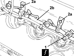
1. Disconnect the electrical connections from the injectors.
| Description | Connector | |
|---|---|---|
| 1 | Injector | See N070 INJECTOR |
2. Undo the bolts (2a) and rmove the electrical wiring (2b) aside.
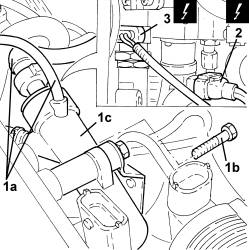
1. Disconnect the pipes (1a), undo the bolts (1b), then remove the fuel return manifold (1c).
2. Disconnect the electrical connection from the fuel pressure regulator on the pressure pump.
| Description | Connector | |
|---|---|---|
| 2 | Pressure regulator on pressure pump | See N077 FUEL PRESSURE REGULATOR |
3. Disconnect the electrical connection from the fuel pressure regulator on the injector single manifold.
| Description | Connector | |
|---|---|---|
| 3 | Fuel pressure regulator on rail | See N087 FUEL PRESSURE REGULATOR ON RAIL |
1. Manually push the clips (1a) and disconnect the pipe from the injectors to the fuel recovery manifold (1b), injector side, and remove it.
2. Undo the connectors securing the pipes from the fuel manifold to the injectors, injector side.
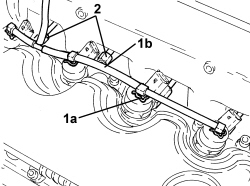
1. Unscrew the connectors (1a) and remove the pipes from the fuel manifold to the injectors (1b).
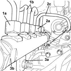
2. Undo the connectors (2a), (2b) and remove the pipe from the pressure pump to the fuel manifold (2c).
3. Undo the nuts (3a) and remove the single fuel manifold assembly pipe (3b).
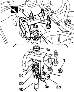
1. Undo the nuts fixing the injector mounting brackets.
2. Position the tool (2a) for extracting the injectors, taking care to position the lifting bracket (2b) under the polygonal area (2c) of the injector.
| Tool | Description | Function | Validity |
|---|---|---|---|
| 1870739000 | Extractor | Removing injectors | 1.9 JTD 8V 1.9 JTD 16V |
3. Position the second tool lifting bracket (3a) under the injector securing bracket (3b).
4. Tighten the tool nut (4a) and remove the injector assembly (4b).
- Repeat the operation for the remaining injectors.
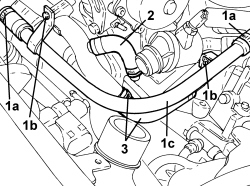
1. Loosen the bands (1a), undo the fastenings (1b) and remove the engine cooling system supply pipe (1c).
2. Loosen the band and disconnect the coolant outlet pipe from the coolant/exhaust gas heat exchanger for the EGR system.
3. Loosen the band and disconnect the coolant return pipe from the engine oil heat exchanger on the water pump rigid inlet pipe side.
1.Loosen the band and disconnect the lower coolant inlet hose from the radiator, water pump rigid coolant inlet pipe side.
2. Undo the upper bolt securing the engine oil dipstick tube.
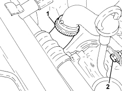
1. Undo the bolts (1a) and remove the side protective timing cover (1b).
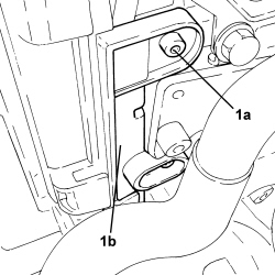
1. Undo the bolts (1a) and remove the water pump inlet pipe (1b).
- Remove the gasket.
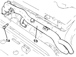
1. Undo the two upper bolts fixing the exhaust manifold heat shield.
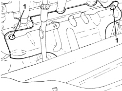
1. Undo the lower bolt securing the engine oil dipstick tube.
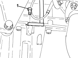
1. Undo the nuts (1a) and the bolt (1b) securing the exhaust manifold heat shield.
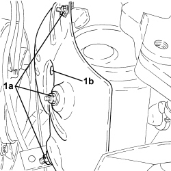
- Working via the engine compartment, remove the pipe for the engine oil dipstick and the exhaust manifold heat shield.
1. Undo the bolts securing the engine oil return pipe from the turbocharger, crankcase side.
2. Undo the connector fastening the engine oil supply pipe to the turbocharger, crankcase side.
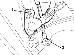
1. Undo the nuts fixing the intermediate exhaust pipe mounting bracket.
2. Undo the nuts (2a) and disconnect the intermediate exhaust pipe (2b) from the catalytic converter.
- Remove the gasket.
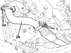
1. Undo the bolts (1a), loosen the collar (1b) and remove the exhaust gas intake pipe from the exhaust manifold to the E.G.R. heat exchanger (1c).
2. Remove the seals.
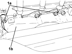
1. Undo the nuts (1a) and move the turbocharger and exhaust manifold assembly (1b) away from the cylinder head.
1. Undo the bolts fixing the exhaust gas outlet hose from the E.G.R. solenoid valve, E.G.R. solenoid valve side.
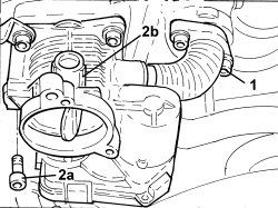
2. Undo the bolts (2a) and remove the throttle body (2b).
- Remove the gasket.
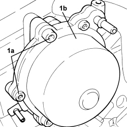
1. Undo the bolts (1a) and remove the vacuum unit (1b).
- Remove the gasket.
1. Loosen the bands and disconnect the pipes from the thermostat.
2. Undo the bolts (2a) and remove the thermostat (2b).
- Remove the gasket.
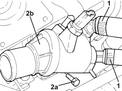
1. Loosen the collar (1a) and disconnect the exhaust gas outlet hose from the exhaust gas/water heat exchanger for the E.G.R. system (1b), heat exchanger side.
2. Undo the fixing bolts (2a) and remove the E.G.R. system solenoid valve (2b) complete with hose.
- Remove the gasket.
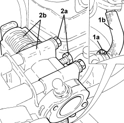
1. Undo the fastenings (1a) and remove the water/exhaust gas heat exchanger for the E.G.R. system (1b).
2. Loosen the band and disconnect the oil vapour pipe from the tappet cover to the crankcase, tappet cover side.
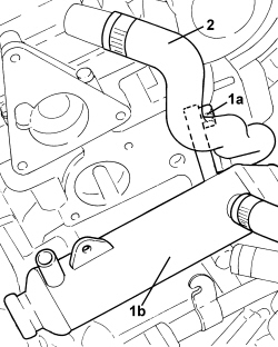
1. Undo the nuts (1a) and remove the vacuum reservoir for the engine air intake management (1b).
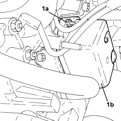
1. Undo the fastenings (1a) and remove the vacuum reservoir mounting (1b).
2. Disconnect the electrical connections from the heater plugs.
| Description | Connector | |
|---|---|---|
| 2 | Heater plugs | See A040 HEATER PLUGS |
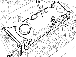
1. Undo the bolts (1a) and remove the cam cover (1b) complete with gasket.
Op. 1008B10 POWER UNIT FRONT SUPPORT FLEXIBLE MOUNTING (TIMING SIDE) - REPLACE
Op. 1032D12 TIMING SYSTEM PROTECTIVE COVER(S) - R + R
Op. 1092G20 ENGINE COMPONENT SINGLE BELT FIXED TENSIONER - ONE - R + R
Op. 1008A46 POWER UNIT RIGID SUPPORT - TIMING SIDE - R.R.
Op. 1032B10 TOOTHED TIMING BELT - R + R FOR TIMING ADJUSTMENT OR REPLACEMENT
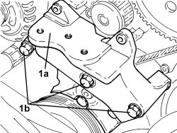
1. Fit the timing side power unit rigid support (1a) temporarily in its housing and secure it using the bolts (1b).
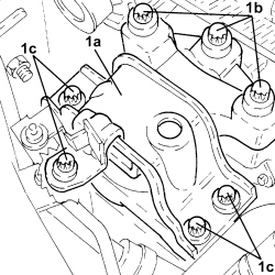
1. Place the flexible mounting for the timing side power unit front support (1a) in its housing temporarily and secure it using the bolts (1b), (1c).
- Remove the hydraulic jack from underneath the front suspension frame.
1. Undo the bolts (1a), (1b) and remove the cylinder head (1c).
2. Remove the cylinder head gasket.
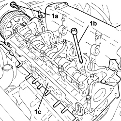
Refitting
- To check the flatness of the lower cylinder head surface and grind if necessary, refer to:
Op. 1016E10 SINGLE CYLINDER HEAD, REMOVED - OVERHAUL
- Refit a new cylinder head gasket in its seat.
If it has not been necessary to level the cylinder head, use a new cylinder head gasket of the same thickness as the old gasket. If the cylinder head required levelling, calculate the thickness of the new cylinder head to be used (see operation 1004E20).
- Position the cylinder head on the cylinder block/crankcase.
1. Tighten the bolts securing the cylinder head to the cylinder block to the recommended torque following the order illustrated and using the angular tightening tool.
| Component | Fastening | dia | Value (daNm) | Validity |
|---|---|---|---|---|
| Cylinder head | Bolt | M12 | (engine crankcase side) 6.2 - 6.8 + 90° + 90° + 90° | 1.9 JTD 8v |
| Tool | Description | Function | Validity |
|---|---|---|---|
| 1860942000 | Torque wrench | Tighten bolts to torque plus angle |
- Tighten the bolt fixing the pressure pump mounting to the cylinder head to the recommended torque.
| Component | Fastening | dia | Value (daNm) | Validity |
|---|---|---|---|---|
| Pressure pump mounting | Bolt | M10 | (cylinder head side) 4.5 - 5.5 | 1.9 JTD 8v |
- Position a hydraulic jack under the front suspension frame.
- Remove the flexible mounting for the timing side power unit front support fitted provisionally.
- Remove the timing side rigid power unit support fitted provisionally.
Op. 1032B10 TOOTHED TIMING BELT - R + R FOR TIMING ADJUSTMENT OR REPLACEMENT
Op. 1008A46 POWER UNIT RIGID SUPPORT - TIMING SIDE - R.R.
Op. 1092G20 ENGINE COMPONENT SINGLE BELT FIXED TENSIONER - ONE - R + R
Op. 1032D12 TIMING SYSTEM PROTECTIVE COVER(S) - R + R
Op. 1008B10 POWER UNIT FRONT SUPPORT FLEXIBLE MOUNTING (TIMING SIDE) - REPLACE
- Place the tappet cover in position and secure it tightening the bolts to the recommended torque.
| Component | Fastening | dia | Value (daNm) | Validity |
|---|---|---|---|---|
| Tappet cover | Bolt | M6 | (cylinder head side) 0.8 - 1.0 | 1.9 JTD 8v |
- Connect the electrical connections to the heater plugs.
-- Place the vacuum reservoir mounting back in its housing and secure it.
- Place the vacuum reservoir for the engine air intake management back in its housing and secure it using the nuts.
- Connect the oil vapour pipe from the tappet cover to the crankcase, tappet cover side and tighten the band.
- Place the exhaust gas/water heat exchanger for the E.G.R. system back in its housing and secure it.
- Place the gasket for the E.G.R. system solenoid valve in its housing.
1. Place the E.G.R. system solenoid valve (1a) complete with hose in its housing and fasten it tightening the bolts (1b) to the recommended torque.
| Component | Fastening | dia | Value (daNm) | Validity |
|---|---|---|---|---|
| E.G.R. system solenoid valve | Bolt | M8 | (intake manifold side) 2.3 - 2.8 | 1.9 JTD 8v |
2. Connect the exhaust gas outlet hose from the exhaust gas/water heat exchanger for the E.G.R. system (2a), heat exchanger side and tighten the collar (2b).
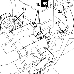
- Place the gasket for the thermostat back in its housing.
1. Place the thermostat (1a) in its housing and fasten it tightening the bolts (1b) to the recommended torque.
| Component | Fastening | dia | Value (daNm) | Validity |
|---|---|---|---|---|
| Thermostat | Bolt | M8 | (cylinder head side) 2.3 - 2.8 | 1.9 JTD 8v |
2. Connect the pipes to the thermostat and tighten the bands.
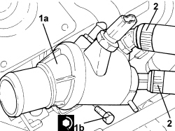
- Place the gasket for the vacuum unit back in its housing.
1. Place the vacuum unit (1a) in its housing and fasten it tightening the bolts (1b) to the recommended torque.
| Component | Fastening | dia | Value (daNm) | Validity |
|---|---|---|---|---|
| Vacuum unit | Bolt | M8 | (cylinder head side) 2.7 - 3.3 | 1.9 JTD 8v |
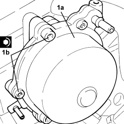
- Place the gasket for the throttle body back in its housing.
1. Place the throttle body (1a) in its housing and secure it tightening the bolts (1b) to the recommended torque.
| Component | Fastening | dia | Value (daNm) | Validity |
|---|---|---|---|---|
| Throttle body | Bolt | (intake manifold side) | 1.9 JTD 8v |
2. Tighten the bolts fixing the exhaust gas outlet hose from the E.G.R. solenoid valve, E.G.R. solenoid valve side.
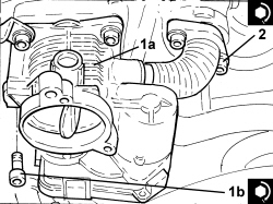
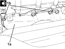
1. Place the turbocharger and exhaust manifold assembly (1a) in its housing and tighten the nuts (1b) to the recommended torque.
| Component | Fastening | dia | Value (daNm) | Validity |
|---|---|---|---|---|
| Turbocharger and exhaust manifold assembly | Nut | M8 | (cylinder head side) 2.2 - 2.7 | 1.9 JTD 8v |
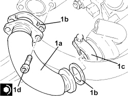
1. Place the exhaust gas intake pipe from the exhaust manifold to the E.G.R. heat exchanger (1a) back in its housing complete with gaskets (1b), then secure it tightening the collar (1c) and the bolts (1d) to the recommended torque.
| Component | Fastening | dia | Value (daNm) | Validity |
|---|---|---|---|---|
| Exhaust gas/water heat exchanger for E.G.R. system | Bolt | M8 | (exhaust manifold side) 2.3 - 2.8 | 1.9 JTD 8v |
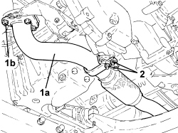
- Place the exhaust pipe gasket in its housing.
1. Connect the intermediate exhaust pipe (1a) to the catalytic converter and tighten the nuts (1b) to the recommended torque.
| Component | Fastening | dia | Value (daNm) | Validity |
|---|---|---|---|---|
| Intermediate exhaust pipe with flexible section | Nut | M8 | (catalytic converter side) 2.2 - 2.6 | 1.9 JTD 16v 1.9 JTD 8v 2.4 JTD 20v |
2. Tighten the nuts securing the intermediate exhaust pipe mounting bracket.
1. Tighten the connector securing the engine oil delivery pipe to the turbocharger, crankcase side to the recommended torque.
| Component | Fastening | dia | Value (daNm) | Validity |
|---|---|---|---|---|
| Engine oil supply pipe to turbocharger | Connector | M12 | (engine crankcase side) 2.2 - 2.7 | 1.9 JTD 16v 1.9 JTD 8v |
2. Tighten the bolts securing the engine oil return pipe from the turbocharger, crankcase side, to the specified torque.
| Component | Fastening | dia | Value (daNm) | Validity |
|---|---|---|---|---|
| Engine oil supply pipe from turbocharger | Bolt | M8 | (engine crankcase side) 2.2 - 2.7 | 1.9 JTD 16v 1.9 JTD 8v |
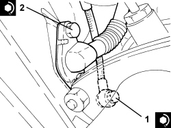
- Working via the engine compartment, place the pipe for the engine oil dipstick and the exhaust manifold heat shield in their housings.
- Tighten the lower nuts and the bolt securing the exhaust manifold heat shield.
- Tighten the lower bolt securing the engine oil dipstick tube.
- Tighten the two upper bolts fixing the exhaust manifold heat shield.
- Place the water pump rigid inlet pipe gasket in its housing.
1. Place the water pump rigid inlet pipe (1a) in position and secure it tightening the bolts (1b) to the recommended torque.
| Component | Fastening | dia | Value (daNm) | Validity |
|---|---|---|---|---|
| Water pump rigid inlet pipe | Bolt | M6 | (cylinder head side) 0.8 - 1.0 | 1.9 JTD 16v 1.9 JTD 8v |
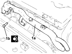
- Fit the timing belt side protective cover and secure it using the bolts.
- Tighten the upper bolt securing the engine oil dipstick tube.
- Connect the lower coolant inlet hose from the radiator, water pump rigid coolant inlet pipe side and tighten the band.
- Connect the return pipe from the engine oil heat exchanger, water pump rigid inlet pipe and tighten the band.
- Connect the coolant oulet pipe from the coolant/exhaust gas heat exchanger for the EGR system and tighten the band.
- Place the engine cooling system supply pipe in its housing, secure it and tighten the bands.
- Place the injectors (1a) in their seats complete with brackets and fasten them tightening the nuts to the recommended torque.
| Component | Fastening | dia | Value (daNm) | Validity |
|---|---|---|---|---|
| Injector brackets | Nut | M8 | (cylinder head side) 2.7 - 3.3 | 1.9 JTD 8v |
1. Place the single fuel manifold pipe (1a) in its housing and secure it tightening the nuts (1b) to the recommended torque.
| Component | Fastening | dia | Value (daNm) | Validity |
|---|---|---|---|---|
| Single fuel manifold pipe (rail) | Nut | M8 | (intake manifold side) 2.3 - 2.8 | 1.9 JTD 8v |
2. Place the pipe from the pressure pump to the fuel manifold pipe (2a) back in its housing and secure it tightening the connectors (2b) and (2c) to the recommended torque.
| Component | Fastening | dia | Value (daNm) | Validity |
|---|---|---|---|---|
| Pipe from pressure pump to fuel manifold | Connector | M12 | (pressure pump side) 2.2 - 2.4 | 1.9 JTD 8v |
| Component | Fastening | dia | Value (daNm) | Validity |
|---|---|---|---|---|
| Pipe from pressure pump to fuel manifold | Connector | M14 | (fuel manifold side) 2.2 - 2.4 | 1.9 JTD 8v |
3. Place the pipes from the fuel manifold to the injectors (3a) in their housings and secure them tightening the connectors (3b) and (3c) to the recommended torque.
| Component | Fastening | dia | Value (daNm) | Validity |
|---|---|---|---|---|
| Pipes from fuel manifold to injectors | Connector | M14 | (fuel manifold side) 2.2 - 2.4 | 1.9 JTD 8v |
| Component | Fastening | dia | Value (daNm) | Validity |
|---|---|---|---|---|
| Pipes from fuel manifold to injectors | Connector | M12 | (injector side) 2.2 - 2.4 | 1.9 JTD 8v |
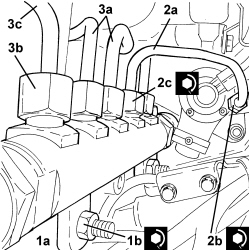
- Place the pipe from the injectors to the fuel recovery manifold in its housing and connect it to the injectors and push home until the clips click into place.
- Connect the electrical connection to the fuel pressure regulator on the injector single manifold.
- Connect the electrical connection to the fuel pressure regulator on the pressure pump.
- Place the fuel return manifold in its housing, secure it using the bolts and connect the pipes.
- Place the electrical wiring in position and fasten it using the bolts.
- Connect the electrical connections to the injectors.
- Connect the electrical connection for the pressure relief sensor.
- Connect the electrical connection to the EGR system solenoid valve
- Place the coolant return pipe to the engine coolant reservoir in position and secure it using the bolts and tighten the bands.
- Connect the electrical connection to the engine coolant temperature sensor.
- Connect the electrical connection to the fuel pressure sensor on the fuel manifold.
- Connect the electrical connection to the throttle casing.
- Place the vacuum pipes in their housings and secure them.
- Connect the vacuum pipe to the vacuum unit.
- Connect the vacuum pipe to the turbocharger vane position actuator control solenoid valve.
- Connect the vacuum pipes to the vacuum reservoir.
- Connect the radiator upper coolant inlet hose, thermostat side, and tighten the band.
- Connect the vacuum pipe rapid connector to the vacuum pump.
- Place the hose and the throttle body rigid air inlet pipe in their housings, then fasten them using the band and the bolts.
- Tighten the coolant drain plug to the radiator.
Op. 1092A10 CRANKSHAFT PULLEY - R + R
Op. 1092G10 SINGLE ENGINE BELT - R.R
Op. 7055B91 RIGHT FRONT WHEEL ARCH LINER - R.R.
Op. 7055B66 ENGINE COMPARTMENT DUST COVER IN RIGHT FRONT WHEEL ARCH - R.R.
Op. 4450B04 RIGHT FRONT WHEEL - R.R
Op. 1048A10 AIR FILTER ASSEMBLY - R.R.
Op. 5530B52 BATTERY SUPPORT/DRIP TRAY - R.R
Op. 1016A10 SOUND-PROOFING COVER - R.R
Op. 0010T20 ENGINE COOLANT - CHANGE
Op. 7055B54 UNDER ENGINE PROTECTION/GUARD - R.R.
- Remove the vehicle from the lift.
- On this version it is not possible to remove/refit the cylinder head on the car.
To perform this operation, remove/refit the power unit
Op. 1004B14 POWER UNIT WITH AUTOMATIC TRANSMISSION R + R
and then work at the bench, customising the engine service procedures for this operation.
Removing
Op. 5530B52 BATTERY SUPPORT/DRIP TRAY - R.R
Op. 0010T20 ENGINE COOLANT - CHANGE
Op. 1032D26 TIMING SYSTEM FRONT PROTECTIVE COVER (UPPER PART) - R.R.
Op. 1032D27 TIMING SYSTEM FRONT PROTECTIVE COVER (LOWER PART) - R.R.
Op. 1092G10 SINGLE ENGINE BELT - R.R
Op. 1092G14 ENGINE COMPONENT SINGLE BELT MOVING TENSIONER - R + R
Op. 1092A10 CRANKSHAFT PULLEY - R + R
Op. 1048A10 AIR FILTER ASSEMBLY - R.R.
Op. 1032B10 TOOTHED TIMING BELT - R + R FOR TIMING ADJUSTMENT OR REPLACEMENT
Op. 1008B10 POWER UNIT FRONT SUPPORT FLEXIBLE MOUNTING (TIMING SIDE) - REPLACE
Op. 1008A46 POWER UNIT RIGID SUPPORT - TIMING SIDE - R.R.
Op. 1084A16 OIL DIPSTICK PIPE - R.R
Op. 1072C44 EXHAUST MANIFOLD HEAT SHIELD - R+R
Op. 1080B94 FRONT LAMBDA SENSOR TO WITH CATALYTIC CONVERTER - R.R
Op. 1072C16 EXHAUST MANIFOLD WITH CATALYTIC CONVERTER - R.R.
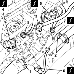
1. Undo the bolts (1a) and remove the rigid coolant pipe (1b) between the thermostat and the engine oil filter mounting.
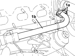
1. Loosen the band and disconnect the radiator coolant supply hose, thermostat side.
2. Loosen the bands and disconnect the heater water supply and return pipes, thermostat mounting side.
3. Disconnect the rapid connector for the throttle body coolant supply pipe, thermostat mounting side.
4. Disconnect the electrical connection for the exhaust side timing sensor.
| Description | Connector | |
|---|---|---|
| 4 | Exhaust side timing sensor | See K107 EXHAUST SIDE TIMING SENSOR |
5. Disconnect the electrical connection for the inlet side timing sensor.
| Description | Connector | |
|---|---|---|
| 5 | Inlet side timing sensor | See K106 INTAKE SIDE TIMING SENSOR |
6. Disconnect the electrical connection for the thermostat temperature regulator.
| Description | Connector | |
|---|---|---|
| 6 | Electronic thermostat | See N086 ELECTRONIC THERMOSTAT |
7. Disconnect the electrical connection for the air temperature sensor.
| Description | Connector | |
|---|---|---|
| 7 | Engine coolant temperature sensor/sender unit | See K036 ENGINE COOLANT TEMPERATURE SENSOR/SENDER UNIT |
8. Undo the bolt securing the earth lead.
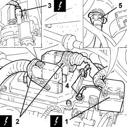
1. Remove the engine intermediate coupling from the bracket.
2. Disconnect the electrical connections for the injection control unit.
| Description | Connector | |
|---|---|---|
| 2 | Engine management control unit | See M010 ENGINE MANAGEMENT ECU |
3. Disconnect the electrical connection for the modular chamber control solenoid valve.
| Description | Connector | |
|---|---|---|
| 3 | Variable geometry solenoid valve | See L015 VARIABLE GEOMETRY SOLENOID VALVE |
4. Undo the bolts and remove the two earth leads from the injection control unit and mounting.
5. Disconnect the brake servo vacuum pipe, modular chamber side.
1. Disconnect the electrical connections for the injectors.
| Description | Connector | |
|---|---|---|
| 1 | Injector | See N070 INJECTOR |
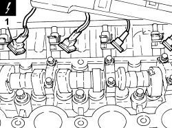
1. Disconnect the electrical connection for the throttle casing.
| Description | Connector | |
|---|---|---|
| 1 | Integrated throttle casing actuator | See N075 THROTTLE BODY ACTUATOR |
2. Disconnect the electrical connection for the fuel vapour solenoid valve.
| Description | Connector | |
|---|---|---|
| 2 | Fuel vapour recovery solenoid valve | See L010 FUEL VAPOUR RECOVERY SOLENOID VALVE |
3. Loosen the band and disconnect the fuel vapour pipes, solenoid valve side.
4. Disconnect the front fuel pipe rapid connector, distribution manifold side.
5. Disconnect the electrical connection for the phase transformer solenoid, inlet side.
| Description | Connector | |
|---|---|---|
| 5 | Inlet side phase transformer solenoid valve | See N092 PHASE SHIFTER SOLENOID VALVE ON INTAKE SIDE |
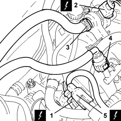
1. Disconnect the electrical connection for the phase transformer solenoid, exhaust side.
| Description | Connector | |
|---|---|---|
| 1 | Exhaust side phase transformer solenoid valve | See N093 PHASE SHIFTER SOLENOID VALVE ON EXHAUST SIDE |
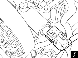
1. Connect the electrical connection for the engine oil pressure switch.
| Description | Connector | |
|---|---|---|
| 1 | Engine oil pressure sensor (switch) | See K030 LOW ENGINE OIL PRESSURE SENSOR (SWITCH) |
2. Disconnect the electrical connection of the air conditioning compressor.
| Description | Connector | |
|---|---|---|
| 2 | Air conditioning compressor engagement electro-magnet | See L020 AIR CONDITIONING COMPRESSOR ENGAGEMENT ELECTRO-MAGNET |
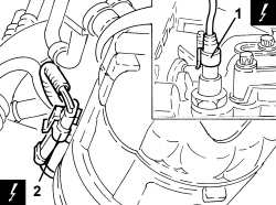
1. Disconnect the electrical connection for the coolant temperature sensor on the radiator.
| Description | Connector | |
|---|---|---|
| 1 | Engine coolant temperature sensor/sender unit | See K036 ENGINE COOLANT TEMPERATURE SENSOR/SENDER UNIT |
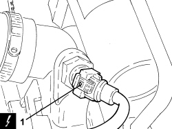
1. Undo the bolt (1a) securing the bracket (1b) to the modular intake chamber.
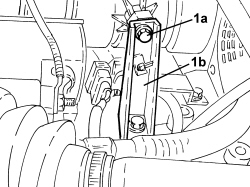
- Disconnect the engine wiring from the intermediate retaining clips.
- Undo the bolts and remove the cylinder head from the engine block.
The bolts should be undone in the order illustrated in the diagram in two distinct stages: firstly loosen all ten bolts by 90° and then by 180°.
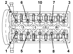
- Remove the gasket.
Refitting
- Clean the cylinder head and engine block matching surfaces thoroughly.
- Check that the planarity of the lower cylinder head plane is within the recommended values, if this is not the case, replace the cylinder head (the cylinder head lower plane cannot be reground).
| Measurement | Value | Validity | ||
|---|---|---|---|---|
| Cylinder head lower surface flatness (mm) | 0.05 | 1.8 2.2 16V | ||
- Place the cylinder head centering bushes in the special openings in the cylinder block.
- Fit a new cylinder head gasket.
- Position the cylinder head on the engine block, ensuring that the valves are closed.
- Tighten the head bolts to the recommended torque in the order illustrated in the diagram.
| Component | Fastening | dia | Value (daNm) | Validity |
|---|---|---|---|---|
| Cylinder head | Bolt (to be replaced) | 2.5 + 90° + 90° + 90° + 45° | 1.8 |
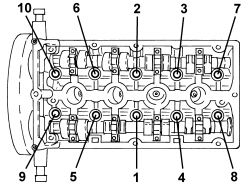
- Secure the engine wiring using the intermediate retaining clips.
- Tighten the bolt securing the bracket to the modulat intake chamber.
- Connect the electrical connection for the coolant temperature sensor on the radiator.
- Connect the electrical connection for the air conditioning compressor.
- Connect the electrical connection for the engine oil pressure switch.
- Connect the electrical connection for the phase transformer solenoid, exhaust side.
- Connect the electrical connection for the phase transformer solenoid, inlet side.
- Connect the front fuel pipe rapid connector, distribution manifold side.
- Connect the fuel vapour pipe, solenoid valve side and tighten the band.
- Connect the electrical connection for the fuel vapour solenoid valve.
- Connect the electrical connection for the throttle casing.
- Connect the electrical connections for the injectors.
- Connect the brake servo vacuum pipe, modular chamber side.
- Place the two earth leads on the injection control unit and mounting and tighten the bolts.
- Connect the electrical connection for the modular chamber control solenoid valve.
- Connect the electrical connections for the injection control unit.
- Place the engine intermediate coupling back in its housing.
- Tighten the bolt securing the earth lead.
- Connect the electrical connection for the coolant temperature sensor.
- Connect the electrical connection for the thermostat temperature regulator.
- Connect the electrical connection for the inlet side timing sensor.
- Connect the electrical connection for the exhaust side timing sensor.
- Connect the rapid connector for the throttle body coolant supply pipe, thermostat mounting side.
- Connect the heater water supply and return pipes, thermostat mounting side and tighten the bands.
- Connect the coolant supply hose to the radiator, thermostat side, and tighten the band.
- Place the rigid coolant pipe between the thermostat and the engine oil filter mounting in position and tighten the bolts.
Op. 1072C16 EXHAUST MANIFOLD WITH CATALYTIC CONVERTER - R.R.
Op. 1080B94 FRONT LAMBDA SENSOR TO WITH CATALYTIC CONVERTER - R.R
Op. 1072C44 EXHAUST MANIFOLD HEAT SHIELD - R+R
Op. 1084A16 OIL DIPSTICK PIPE - R.R
Op. 1008A46 POWER UNIT RIGID SUPPORT - TIMING SIDE - R.R.
Op. 1008B10 POWER UNIT FRONT SUPPORT FLEXIBLE MOUNTING (TIMING SIDE) - REPLACE
Op. 1032B10 TOOTHED TIMING BELT - R + R FOR TIMING ADJUSTMENT OR REPLACEMENT
Op. 1048A10 AIR FILTER ASSEMBLY - R.R.
Op. 1092A10 CRANKSHAFT PULLEY - R + R
Op. 1092G14 ENGINE COMPONENT SINGLE BELT MOVING TENSIONER - R + R
Op. 1092G10 SINGLE ENGINE BELT - R.R
Op. 1032D27 TIMING SYSTEM FRONT PROTECTIVE COVER (LOWER PART) - R.R.
Op. 1032D26 TIMING SYSTEM FRONT PROTECTIVE COVER (UPPER PART) - R.R.
Op. 0010T20 ENGINE COOLANT - CHANGE
Parts & tools for this job For 2005 Fiat Croma
- PARTEngine gasket setSearch: Fiat Croma 2005 engine gasket set
- TOOLTorque wrenchSearch: 3/8 inch torque wrench
- TOOLFeeler gauge setSearch: feeler gauge set
Links open Amazon search results in a new tab. As an Amazon Associate I earn from qualifying purchases.