
Selector and Inhibitor Switch (Automatic gearbox - Jatco)
- Make
- Land Rover
- Model
- Freelander System Description and Operation (UK)
- Section
- Description and operation › Selector and Inhibitor Switch
The EAT ECU will detect temperature sensor failure when the vehicle speed exceeds 12.5 mph (20 km/h) and the temperature sensor provides a reading of less than -30°C (-22°F). In the event of a fluid temperature sensor signal failure any of the following symptoms may be observed: l Upshift to 5th gear inoperative l Torque reduction request from the EAT ECU to the ECM inoperative.
Selector and Inhibitor Switch
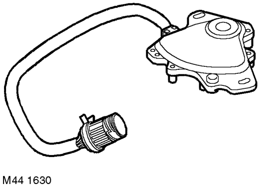
The selector and inhibitor switch is located on the selector shaft on top of the gearbox and connected to the main harness by a 10 pin connector (C0244).
While the ignition is on, the selector and inhibitor switch receives a battery voltage power feed from the main relay. In some markets, in order to illuminate the LED module whenever the key is in the ignition switch, the selector and inhibitor switch also receives a battery voltage power feed from an illumination relay installed behind the centre console.
Where fitted, operation of the illumination relay is controlled by the passive coil on the ignition switch. When the key is installed in the ignition switch the illumination relay energises to connect the power feed to the selector and inhibitor switch. When the main relay is energised by the ECM, the illumination relay de-energises and the power feed to the selector and inhibitor switch is taken from the main relay.
The EAT ECU and the LED module are provided with a voltage output from the selector and inhibitor switch that corresponds with the gear position the driver has selected. Seven sets of contacts in the selector and inhibitor switch which are operated by the selector shaft. Each set of contacts corresponds to one of the seven selector lever positions (PRND421). Only one set of contacts will supply battery voltage to the EAT ECU and the LED module at any one time. The EAT ECU monitors the switch outputs every 10 ms.
A pair of contacts are provided for the crank inhibit circuit. The contacts are only closed when the selector lever is in the 'P' and 'N' positions.
The two contacts are wired in series with the EWS3D immobilisation ECU. When the selector lever is in any position other than 'P' or 'N', the feed from the ignition switch to the immobilisation ECU is broken by the open contacts, preventing starter motor operation.
In the event of a selector and inhibitor switch signal failure, any of the following symptoms may be observed: l Upshift to 5th gear inoperative l Torque converter lock-up inoperative l Torque reduction request from the EAT ECU to the ECM inoperative l Cranking disabled if fault is on the two inhibitor switch contacts.
Parts & tools for this job For Land Rover Freelander
- TOOLOBD2 scannerSearch: OBD2 scanner
- TOOLDigital multimeterSearch: automotive digital multimeter
- TOOLBack-probe test leadsSearch: back probe test leads
Links open Amazon search results in a new tab. As an Amazon Associate I earn from qualifying purchases.