
Steering (Valve Unit): Description and operation
- Make
- Land Rover
- Model
- Freelander System Description and Operation (UK)
- Section
- Description and operation › Valve Unit
Valve Unit
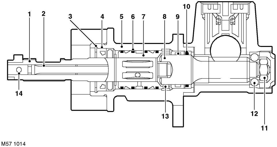
1 Input shaft 2 Torsion bar 3 Circlip 4 Oil seal 5 Valve housing 6 PTFE ring (4 off) 7 Outer sleeve
8 Pinion shaft 9 Bearing 10 Oil seal 11 Nut 12 Bearing 13 Pin - pinion shaft to outer sleeve 14 Pin - input shaft to torsion bar
The valve unit is an integral part of the steering rack. The principal function of the valve unit is to provide maximum power assistance (i.e. when parking) with minimum effort required to turn the steering wheel.
The cast outer casing of the valve unit has four ports which provide the connections for pressure feed from the PAS pump, return to the fluid reservoir and pressure feeds from the valve unit to the annulus area and the full area of the cylinder. A non return valve and seal is fitted in the pressure feed port from the PAS pump.
The valve unit comprises an outer sleeve, input shaft, torsion bar and a pinion shaft. The valve unit is coaxial with the pinion shaft which is connected to the steering column via the input shaft. The valve unit components are located in a housing which is attached to a mating casting on the steering rack main body and secured with screws.
The outer sleeve is located in the main bore of the valve unit. Three annular grooves are machined on its outer diameter. PTFE rings are located between the grooves and seal against the bore of the valve unit. Holes are drilled radially in each annular groove through the wall of the sleeve. The bore of the outer sleeve is machined to accept the input shaft. Six equally spaced slots are machined in the bore of the sleeve. The ends of the slots are closed and do not continue to the ends of the outer sleeve. The radial holes in the outer sleeve are drilled into each slot.
The input shaft is splined at its outer end. The inner end of the input shaft forms a dog-tooth which mates with a slot in the pinion shaft. The fit of the dog-tooth in the slot allows a small amount of relative rotation between the input shaft and the pinion shaft before the dog-tooth contacts the wall of the slot. This ensures that, if the power assistance fails, the steering can be operated manually without over stressing the torsion bar. The central portion of the input shaft has equally spaced longitudinal slots machined in its circumference. The slots are arranged alternately around the input shaft.
The torsion bar is fitted inside the input shaft and is an interference fit in the pinion. The torsion bar is connected to the input shaft by a drive pin, fitted after hydraulic balancing. The central diameter of the torsion bar is machined to a smaller diameter than at each end. The smaller diameter allows the torsion bar to twist in response to torque applied from the steering wheel in relation to the grip of the tyres on the road surface.
The pinion shaft has machined teeth on its central diameter which mate with the teeth on the steering rack. A slot machined in the upper end of the pinion shaft mates with the dog-tooth on the input shaft. The pinion shaft locates in a cast housing which is part of the steering rack and rotates on ball and roller bearings.
Parts & tools for this job For Land Rover Freelander
- PARTEngine gasket setSearch: Land Rover Freelander engine gasket set
- TOOLTorque wrenchSearch: 3/8 inch torque wrench
- TOOLFeeler gauge setSearch: feeler gauge set
Links open Amazon search results in a new tab. As an Amazon Associate I earn from qualifying purchases.