
Gearbox assembly (page 5 of 6)
- Make
- Rover
- Model
- 100 Repair Manual Supplement
- Year
- 1996–1998
- Section
- Repairs
Manual gearboxGearbox assembly · page 5 of 6
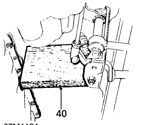
- Lever power unit forward approximately 25 mm and insert wooden block, measuring 150 mm x 80 mm, lengthways between engine and subframe to hold power unit forward.
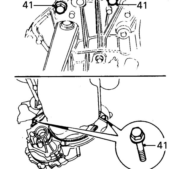
- Remove 4 bolts securing gearbox to engine.
- Release gearbox from engine, raise and manoeuvre gearbox clear of engine compartment.
Refit
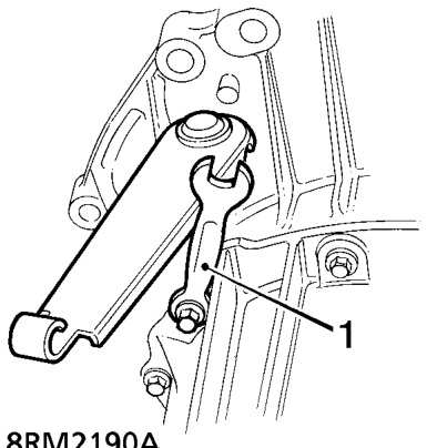
- Use gear case bolt to secure small open ended spanner in position illustrated to prevent clutch release lever moving.
- Connect lifting equipment to gearbox.
- Lower gearbox into engine compartment and secure on dowels.
- Fit bolts securing gearbox and tighten to 85 Nm.
- Remove jack, lever power unit forward and remove block from between engine and subframe.
- Position LH mounting bracket to gearbox, fit bolts and tighten to 80 Nm.
- Position support member to subframe, fit bolts and tighten to 45 Nm.
- Adjust height of power unit to align mounting bracket to LH engine mounting, fit bolts and tighten to 45 Nm.
- Remove lifting equipment.
- Position harness to support member and secure clip.
- Fit both drive shaft and hub assemblies. See REPAIR MANUAL - Manual Gearbox - Differential Oil Seal.
- Position flywheel rear cover plate, align harness bracket, fit 2 small bolts and tighten to 8 Nm.Tighten large nut and bolt to 38 Nm.
- Position flywheel front cover plate, fit bolts and tighten to 8 Nm.
- Position flywheel lower cover plate, fit bolts and tighten to 8 Nm.
Parts & tools for this job For 1996 Rover 100
- PARTClutch kitSearch: Rover 100 1996 clutch kit
- TOOLClutch alignment toolSearch: clutch alignment tool
- FLUIDGear oilSearch: Rover 100 manual gearbox oil
Links open Amazon search results in a new tab. As an Amazon Associate I earn from qualifying purchases.