
Clutch assembly and release bearing - ’l’ series
- Make
- Rover
- Model
- 400 Workshop Manual
- Year
- 1995–2000
- Section
- Repairs › Clutch assembly and release bearing - ’l’ series
ClutchClutch assembly and release bearing - ’l’ series · page 1 of 3
Refit
- Clean pressure plate and flywheel, dowels and dowel holes.
- Inspect flywheel for signs of scoring or other damage. Renew if worn or damaged.
- Smear clutch drive plate splines with molybdenum disulphide grease.
- Position drive plate to flywheel with ’FLYWHEEL SIDE’ marking towards flywheel.
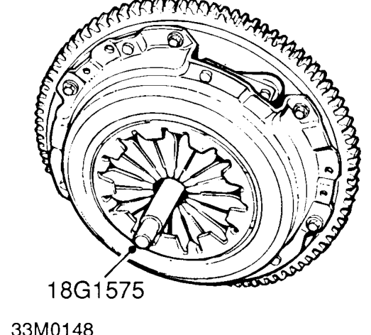
- Fit pressure plate to flywheel and fit alignment tool 18G 1575 .
- Fit 6 Torx bolts securing pressure plate to flywheel finger tight.
- Working in a diagonal sequence, progressively tighten Torx bolts to 18 Nm.
- Remove drive plate alignment tool 18G 1575 .
- Remove 2 bolts securing flywheel locking tool 18G 1571 to engine and remove flywheel locking tool.
- Clean clutch release fork and release bearing guide sleeve.
- Smear release fork shaft and bore of release bearing with Molybdenum disulphide grease.
- Fit release bearing to release fork and slide onto guide sleeve.
- Operate release lever to ensure that release bearing is correctly located on release fork and slides smoothly on guide sleeve.
- Fit gearbox assembly. See MANUAL GEARBOX - ’R65’, Repairs.
CLUTCH ASSEMBLY AND RELEASE BEARING - ’L’ SERIES
Service repair no - 33.10.07
Remove
- Remove gearbox assembly. See MANUAL GEARBOX - ’PG1’, Repairs.
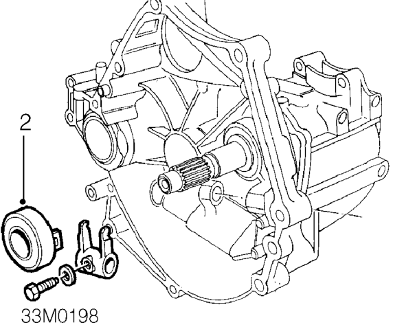
- Remove release bearing from guide sleeve and release fork.
- Examine release bearing for signs of wear or damage, renew if necessary.
CAUTION: Bearing is packed with grease, DO NOT wash in solvent.
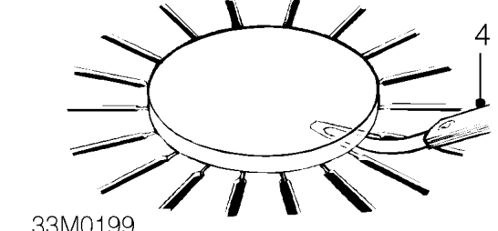
- Place a circular piece of flat plate across diaphragm fingers and insert feeler gauges between plate and fingers.
Diaphragm finger clearance limit = 1.0 mm
Parts & tools for this job For 1995 Rover 400
- PARTClutch kitSearch: Rover 400 1995 clutch kit
- TOOLClutch alignment toolSearch: clutch alignment tool
- FLUIDGear oilSearch: Rover 400 manual gearbox oil
Links open Amazon search results in a new tab. As an Amazon Associate I earn from qualifying purchases.