
Operation (clutch applied)
- Make
- Rover
- Model
- 600 Rover 600 Repair Manual - Volumes 1 and 2 - 2nd Edition
- Section
- Information › Operation (clutch applied)
Automatic gearboxOperation (clutch applied)
Operation (clutch applied)
With the lock-up clutch applied, the oil in the chamber between the converter cover and lock-up piston is drained off and the converter oil exerts pressure through the piston against the converter cover. As a result, the turbine is locked to the converter cover. The effect is to bypass the converter, thereby placing the vehicle in direct drive.
Power flow.
The power flows by way of:
| Engine |
| Drive plate |
| Torque converter cover |
| Lock up piston |
| Damper spring |
| Turbine |
| Mainshaft |
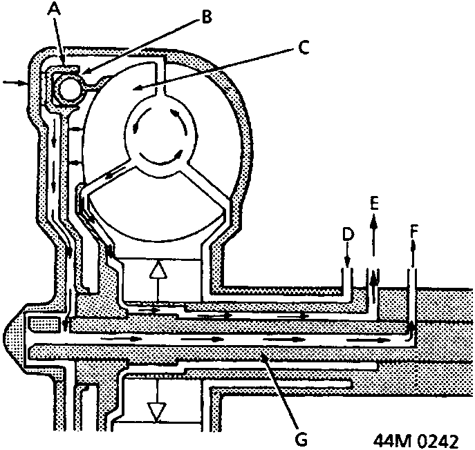
- A Lock-up piston
- B Damper spring
- C Turbine
- D Oil inlet
- E To oil cooler
- F Oil outlet
- G Mainshaft
- H Torque converter cover
Original page
Parts & tools for this job For Rover 600
- PARTClutch kitSearch: Rover 600 clutch kit
- TOOLClutch alignment toolSearch: clutch alignment tool
- FLUIDGear oilSearch: Rover 600 manual gearbox oil
Links open Amazon search results in a new tab. As an Amazon Associate I earn from qualifying purchases.