
Shift control
- Make
- Rover
- Model
- 600 Rover 600 Repair Manual - Volumes 1 and 2 - 2nd Edition
- Section
- Information › Shift control
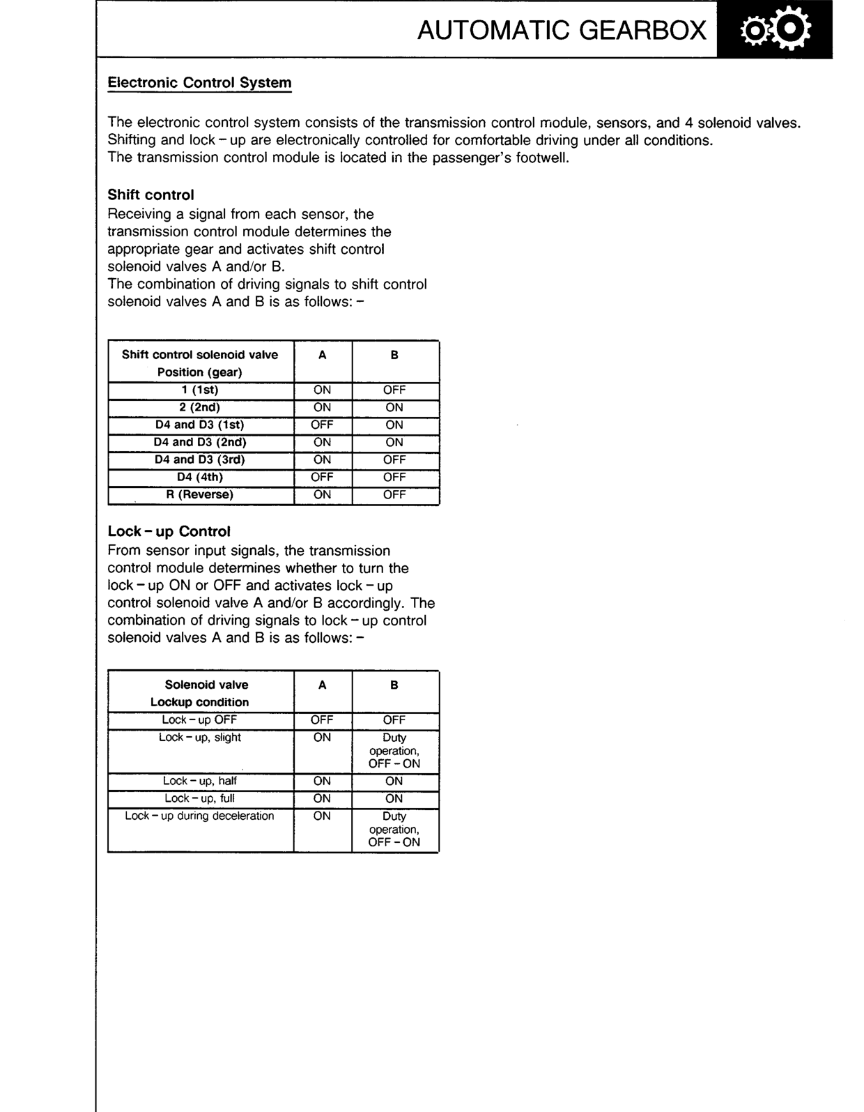
The electronic control system consists of the transmission control module, sensors, and 4 solenoid valves. Shifting and lock – up are electronically controlled for comfortable driving under all conditions. The transmission control module is located in the passenger’s footwell.
Shift control
Receiving a signal from each sensor, the transmission control module determines the appropriate gear and activates shift control solenoid valves A and/or B.
The combination of driving signals to shift control solenoid valves A and B is as follows: –
| Shift control solenoid valve Position (gear) | A | B |
|---|---|---|
| 1 (1st) | ON | OFF |
| 2 (2nd) | ON | ON |
| D4 and D3 (1st) | OFF | ON |
| D4 and D3 (2nd) | ON | ON |
| D4 and D3 (3rd) | ON | OFF |
| D4 (4th) | OFF | OFF |
| R (Reverse) | ON | OFF |
Lock – up Control
From sensor input signals, the transmission control module determines whether to turn the lock – up ON or OFF and activates lock – up control solenoid valve A and/or B accordingly. The combination of driving signals to lock – up control solenoid valves A and B is as follows: –
| Solenoid valve Lockup condition | A | B |
|---|---|---|
| Lock – up OFF | OFF | OFF |
| Lock – up, slight | ON | Duty operation, OFF – ON |
| Lock – up, half | ON | ON |
| Lock – up, full | ON | ON |
| Lock – up during deceleration | ON | Duty operation, OFF – ON |
Original page
Parts & tools for this job For Rover 600
- PARTTransmission filter kitSearch: Rover 600 transmission filter kit
- FLUIDAutomatic transmission fluidSearch: Rover automatic transmission fluid
- TOOLFluid transfer pumpSearch: fluid transfer pump
Links open Amazon search results in a new tab. As an Amazon Associate I earn from qualifying purchases.