
Operation (clutch released) (page 2 of 2)
- Make
- Rover
- Model
- 600 Rover 600 Repair Manual - Volumes 1 and 2 - 2nd Edition
- Section
- Information
Automatic gearboxOperation (clutch released) · page 2 of 2
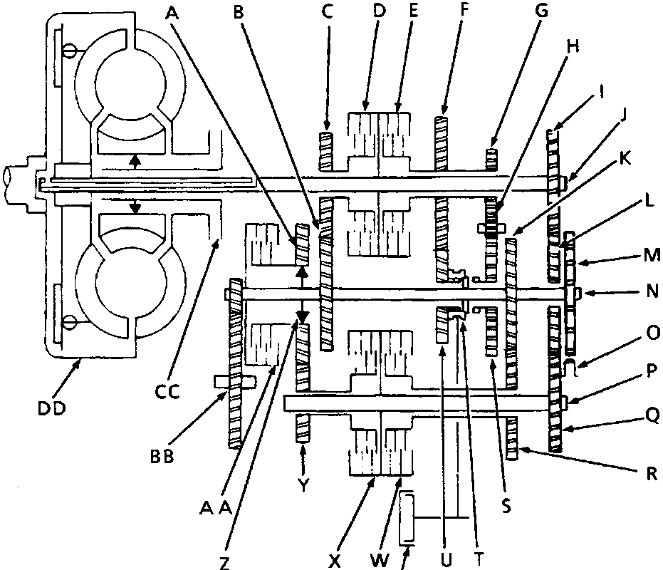
44M 0244
| A Countershaft 1st gear | P Secondary shaft |
| B Countershaft 3rd gear | Q Secondary shaft idler gear |
| C Mainshaft 3rd gear | R Secondary shaft 2nd gear |
| D 3rd clutch | S Countershaft reverse gear |
| E 4th clutch | T Reverse selector |
| F Mainshaft 4th gear | U Countershaft 4th gear |
| G Mainshaft reverse gear | V Servo valve |
| H Reverse idler gear | W 2nd clutch |
| I Mainshaft idler gear | X 1st clutch |
| J Mainshaft | Y Secondary shaft 1st gear |
| K Countershaft 2nd gear | Z One way clutch |
| L Countershaft idler gear | AA 1st hold clutch |
| M Parking gear | BB Final driven gear |
| N Countershaft | CC Impeller |
| O Parking pawl | DD Torque converter |
Parts & tools for this job For Rover 600
- PARTClutch kitSearch: Rover 600 clutch kit
- TOOLClutch alignment toolSearch: clutch alignment tool
- FLUIDGear oilSearch: Rover 600 manual gearbox oil
Links open Amazon search results in a new tab. As an Amazon Associate I earn from qualifying purchases.