
Component location
- Make
- Rover
- Model
- 600 Rover 600 Repair Manual - Volumes 1 and 2 - 2nd Edition
- Section
- Information › Component location
Automatic gearboxComponent location · page 1 of 5
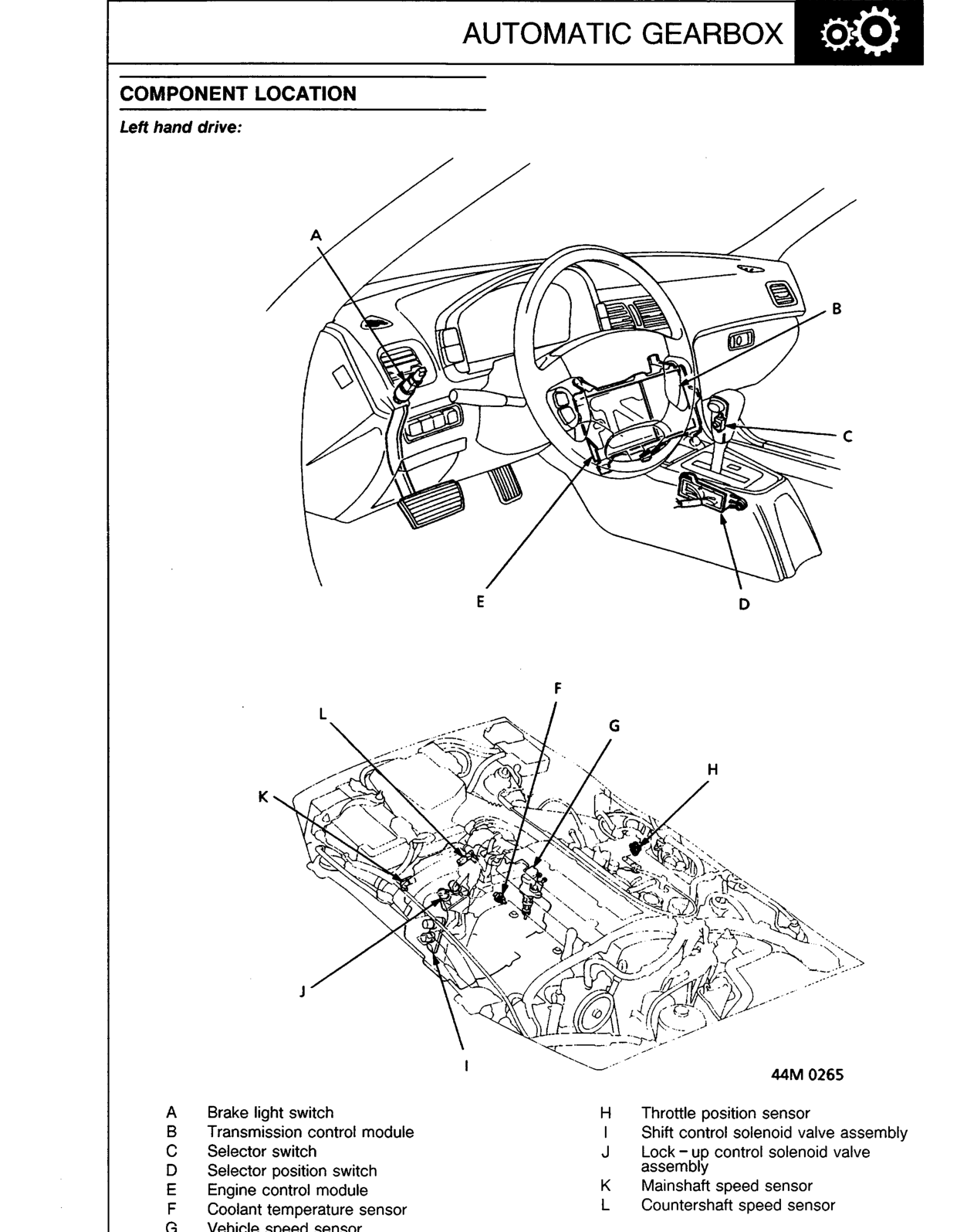
COMPONENT LOCATION
Left hand drive:
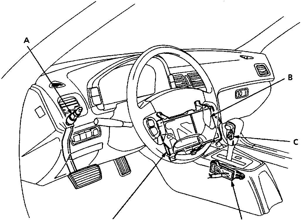
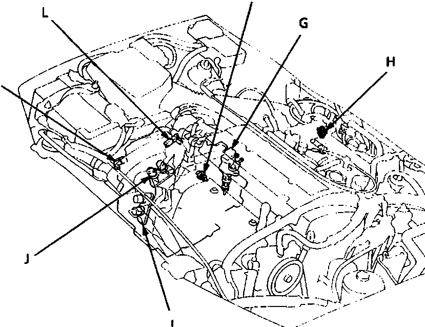
44M 0265
| A | Brake light switch | H | Throttle position sensor |
| B | Transmission control module | I | Shift control solenoid valve assembly |
| C | Selector switch | J | Lock – up control solenoid valve assembly |
| D | Selector position switch | K | Mainshaft speed sensor |
| E | Engine control module | L | Countershaft speed sensor |
| F | Coolant temperature sensor | ||
| G | Vehicle speed sensor |
Original page
Parts & tools for this job For Rover 600
- PARTTransmission filter kitSearch: Rover 600 transmission filter kit
- FLUIDAutomatic transmission fluidSearch: Rover automatic transmission fluid
- TOOLFluid transfer pumpSearch: fluid transfer pump
Links open Amazon search results in a new tab. As an Amazon Associate I earn from qualifying purchases.