
Regulator Valve
- Make
- Rover
- Model
- 600 Rover 600 Repair Manual - Volumes 1 and 2 - 2nd Edition
- Section
- Information › Regulator Valve
Regulator Valve
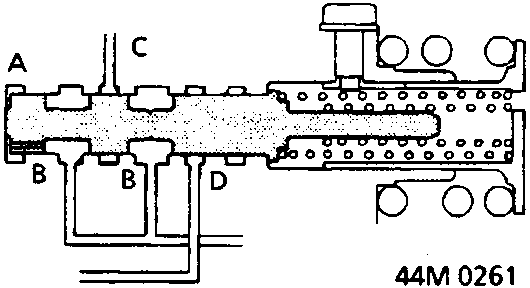
The regulator valve maintains a constant hydraulic pressure delivered by the pump to the hydraulic control system, the lubricating system and torque converter. Fluid flows through B and B'. The fluid which enters through B flows through the valve orifice to A, moving the regulator valve to the right. Depending on the amount of hydraulic pressure delivered through B, the position of the valve changes and the flow through B' from D also changes. This operation is continued, maintaining line pressure.
ENGINE NOT RUNNING
ENGINE RUNNING
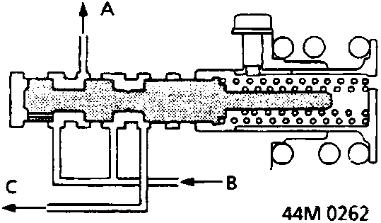
A To torque converter
B From pump
C To relief valve
Stator Reaction Hydraulic Pressure Control
Hydraulic pressure increase, depending on amount of torque applied, is performed by the regulator valve using stator torque reaction. One end of the stator shaft is splined to the stator. An arm attached to the other end of the stator shaft is in contact with the regulator valve spring cap and forms a reaction member between the stator shaft and the regulator valve. When the vehicle is accelerating or climbing (Torque Converter Range), stator torque reaction acts on the stator shaft causing the stator shaft arm to move and compress the stator reaction spring. This causes the regulator valve to move and allow increased regulated control or line pressure. Line pressure is maximum when the stator torque reaction is greatest.
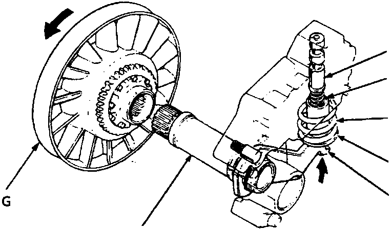
- A Regulator valve
- B Regulator spring
- C Stator reaction spring
- D Regulator valve spring cap
- E Stator shaft arm
- F Stator shaft
- G Stator
Parts & tools for this job For Rover 600
- PARTEngine gasket setSearch: Rover 600 engine gasket set
- TOOLTorque wrenchSearch: 3/8 inch torque wrench
- TOOLFeeler gauge setSearch: feeler gauge set
Links open Amazon search results in a new tab. As an Amazon Associate I earn from qualifying purchases.