
Inspection
- Make
- Rover
- Model
- 600 Rover 600 Repair Manual - Volumes 1 and 2 - 2nd Edition
- Section
- Repairs › Inspection
SuspensionInspection
Inspection
- Raise the car and set the turning radius gauges beneath the rear wheels and place boards under the front wheels the same thickness as one of the turning radius gauges, then lower the car.
Note: Be sure that the car is parallel to the ground with the wheels on the turning radius gauges and boards.
- Release parking brake.
Note: If the parking brake is engaged, you may get an incorrect reading.
- Check the rear toe.
Rear toe – in: 2.0 ± 2.0mm (0.08 ± 0.08in)
- If out of specification, adjust the rear toe.
Adjustment
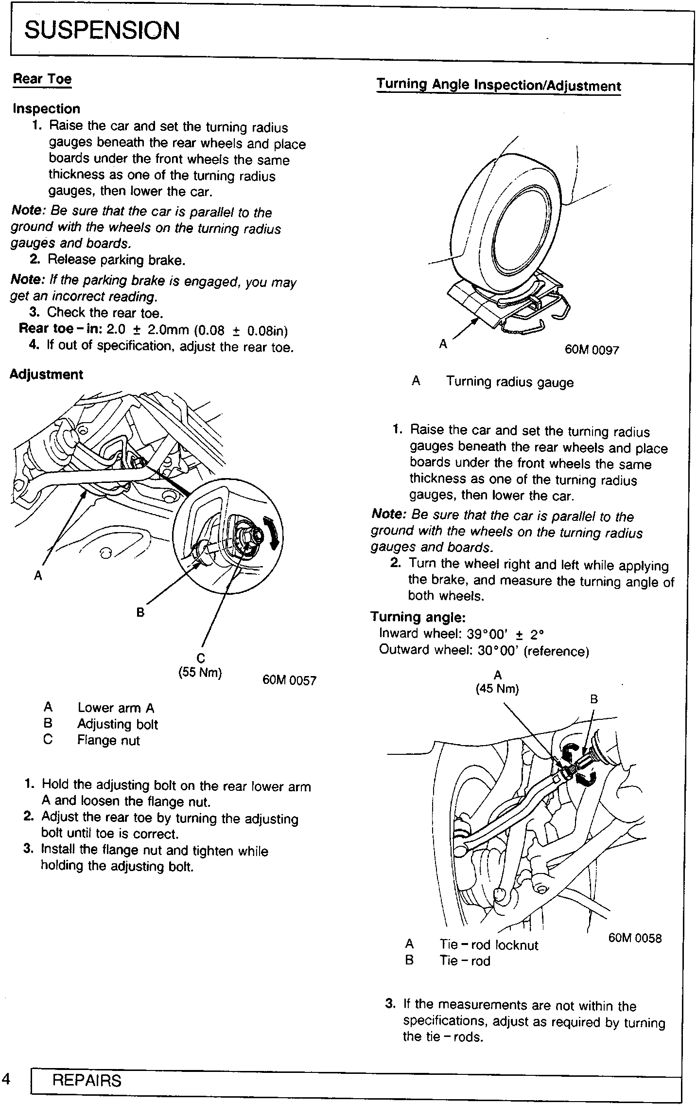
- Lower arm A
- Adjusting bolt
- Flange nut
- Hold the adjusting bolt on the rear lower arm A and loosen the flange nut.
- Adjust the rear toe by turning the adjusting bolt until toe is correct.
- Install the flange nut and tighten while holding the adjusting bolt.
Turning Angle Inspection/Adjustment
- Turning radius gauge
- Raise the car and set the turning radius gauges beneath the rear wheels and place boards under the front wheels the same thickness as one of the turning radius gauges, then lower the car.
Note: Be sure that the car is parallel to the ground with the wheels on the turning radius gauges and boards.
- Turn the wheel right and left while applying the brake, and measure the turning angle of both wheels.
Turning angle:
Inward wheel: 39°00' ± 2°
Outward wheel: 30°00' (reference)
- Tie – rod locknut
- Tie – rod
- If the measurements are not within the specifications, adjust as required by turning the tie – rods.
Parts & tools for this job For Rover 600
- TOOLCoil spring compressorSearch: coil spring compressor
- TOOLBall joint separatorSearch: ball joint separator
- PARTShock absorbersSearch: Rover 600 shock absorbers
Links open Amazon search results in a new tab. As an Amazon Associate I earn from qualifying purchases.