
Adjustment
- Make
- Rover
- Model
- 600 Rover 600 Repair Manual - Volumes 1 and 2 - 2nd Edition
- Section
- Repairs › Adjustment
SuspensionAdjustment
Adjustment
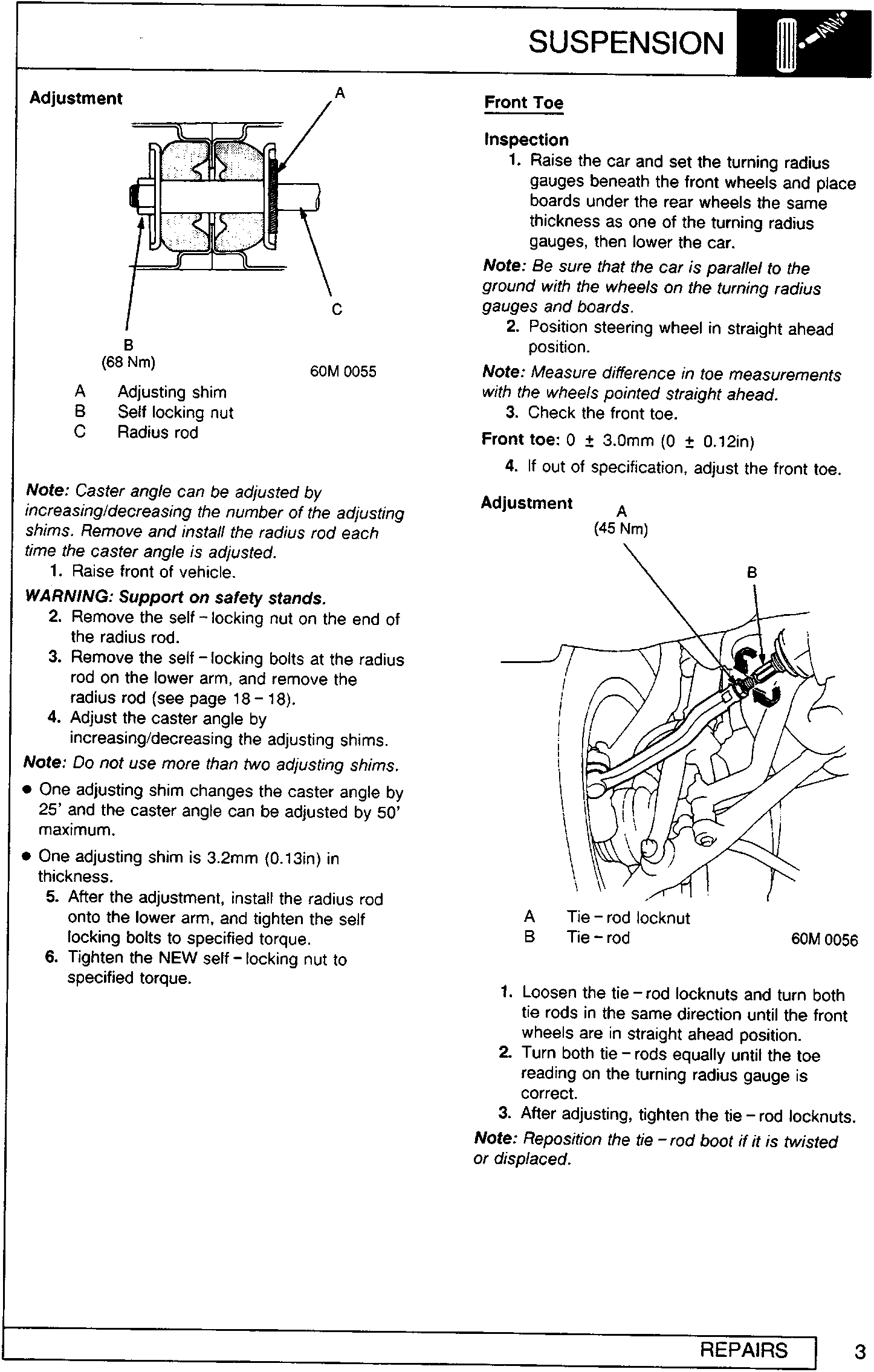
- A Adjusting shim
- B Self locking nut
- C Radius rod
Note: Caster angle can be adjusted by increasing/decreasing the number of the adjusting shims. Remove and install the radius rod each time the caster angle is adjusted.
- Raise front of vehicle.
WARNING: Support on safety stands.
- Remove the self – locking nut on the end of the radius rod.
- Remove the self – locking bolts at the radius rod on the lower arm, and remove the radius rod (see page 18 – 18).
- Adjust the caster angle by increasing/decreasing the adjusting shims.
Note: Do not use more than two adjusting shims.
- One adjusting shim changes the caster angle by 25' and the caster angle can be adjusted by 50' maximum.
- One adjusting shim is 3.2mm (0.13in) in thickness.
- After the adjustment, install the radius rod onto the lower arm, and tighten the self locking bolts to specified torque.
- Tighten the NEW self – locking nut to specified torque.
Front Toe
Inspection
- Raise the car and set the turning radius gauges beneath the front wheels and place boards under the rear wheels the same thickness as one of the turning radius gauges, then lower the car.
Note: Be sure that the car is parallel to the ground with the wheels on the turning radius gauges and boards.
- Position steering wheel in straight ahead position.
Note: Measure difference in toe measurements with the wheels pointed straight ahead.
- Check the front toe.
Front toe: 0 ± 3.0mm (0 ± 0.12in)
- If out of specification, adjust the front toe.
Adjustment
- A Tie – rod locknut
- B Tie – rod
- Loosen the tie – rod locknuts and turn both tie rods in the same direction until the front wheels are in straight ahead position.
- Turn both tie – rods equally until the toe reading on the turning radius gauge is correct.
- After adjusting, tighten the tie – rod locknuts.
Note: Reposition the tie – rod boot if it is twisted or displaced.
Parts & tools for this job For Rover 600
- TOOLCoil spring compressorSearch: coil spring compressor
- TOOLBall joint separatorSearch: ball joint separator
- PARTShock absorbersSearch: Rover 600 shock absorbers
Links open Amazon search results in a new tab. As an Amazon Associate I earn from qualifying purchases.