
Remove
- Make
- Rover
- Model
- Coupé, Cabriolet & Tourer 200/400 Coupé, Cabriolet & Tourer Workshop Manual
- Section
- Repairs › Remove
Engine 2.0 T16Remove · page 1 of 2
Service Repair No. 12.29.02
Remove
- Disconnect battery earth lead.
- Remove air cleaner, see MODULAR ENGINE MANAGEMENT SYSTEM – Repairs – MPi.
- Drain cooling system, see MAINTENANCE.
Turbo models
- Remove intercooler, see MODULAR ENGINE MANAGEMENT SYSTEM – Repairs.
- Remove alternator, see ELECTRICAL – Repairs.
- Remove exhaust manifold and turbocharger, see MANIFOLD & EXHAUST – Repairs.
- Disconnect camshaft sensor multiplug.
All models
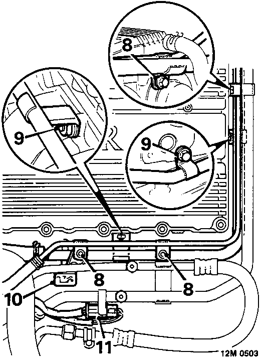
Air conditioning model illustrated
- Remove 3 bolts securing expansion tank rail to coolant rail and cylinder head.
- Remove nut and bolt securing coolant rail to cylinder head.
- Remove dipstick tube.
- Disconnect oxygen sensor multiplug.
- Release multiplug from air conditioning pipe (thermostat housing on naturally aspirated models) and position aside.
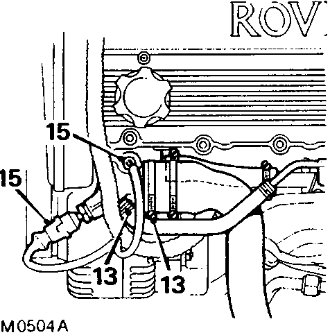
- Slacken clips and disconnect hoses from:
Air conditioning: Outlet elbow.
Non air conditioning: Thermostat housing. - Move coolant rail and expansion tank rail aside.
- Disconnect coolant thermistor and temperature gauge sensor.
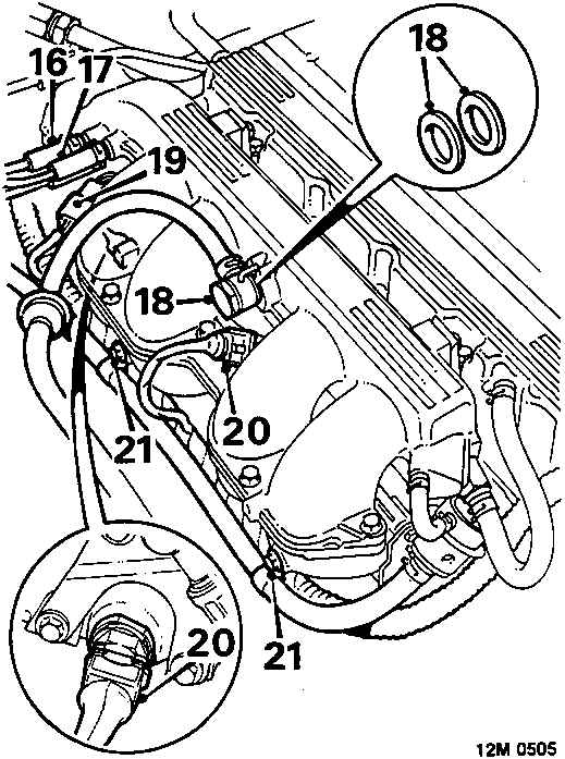
- Disconnect E.C.U. pressure sensing hose from inlet manifold.
- Release clip and disconnect vacuum hose from inlet manifold.
- Remove banjo bolt from manifold chamber and collect sealing washers.
- Disconnect injector harness multiplug.
- Disconnect fuel temperature and inlet air temperature sensor multiplugs.
- Remove 2 bolts securing harness to inlet manifold.
- Place engine harness aside, clear of cylinder head.
Parts & tools for this job For Rover Coupé, Cabriolet & Tourer
- PARTEngine gasket setSearch: Rover Coupé, Cabriolet & Tourer engine gasket set
- TOOLTorque wrenchSearch: 3/8 inch torque wrench
- TOOLFeeler gauge setSearch: feeler gauge set
Links open Amazon search results in a new tab. As an Amazon Associate I earn from qualifying purchases.