
Engine and manual gearbox
- Make
- Rover
- Model
- Coupé, Cabriolet & Tourer 200/400 Coupé, Cabriolet & Tourer Workshop Manual
- Section
- Repairs › Engine and manual gearbox
Engine 2.0 T16Engine and manual gearbox · page 1 of 5
- Run engine.
- Check for leakage around sump joint and top – up engine oil if necessary.
ENGINE AND MANUAL GEARBOX
Service Repair No. 12.37.01
Note: On models fitted with air conditioning:
- Reclaim refrigerant, see AIR CONDITIONING – Adjustments, then see Repairs for the following;
- Disconnect union, evaporator hose to compressor.
- Remove pipe, compressor to condenser.
- Remove bolts securing air conditioning pipe bracket to bonnet platform.
- Remove receiver drier.
Remove
- Disconnect battery earth lead.
- Remove air cleaner, see MODULAR ENGINE MANAGEMENT SYSTEM – Repairs.
- Drain cooling system, see MAINTENANCE.
- Turbo models: Remove intercooler, see MODULAR ENGINE MANAGEMENT SYSTEM – Repairs.
- Naturally aspirated models without air conditioning: Remove radiator, see COOLING SYSTEM – Repairs.
- Remove exhaust front pipe, see MANIFOLD & EXHAUST – Repairs.
- Remove bonnet, see BODY – Repairs.
- Drain gearbox oil, see MAINTENANCE.
- Drain engine oil, see MAINTENANCE.
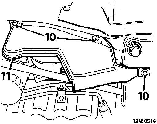
- Remove 3 bolts securing R.H. splash shield.
- Remove splash shield.
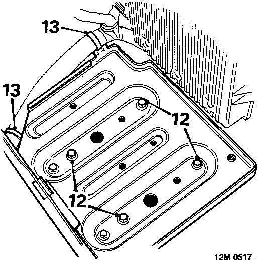
- Remove 4 bolts securing battery tray.
- Release 2 clips securing harness to battery tray, remove tray.
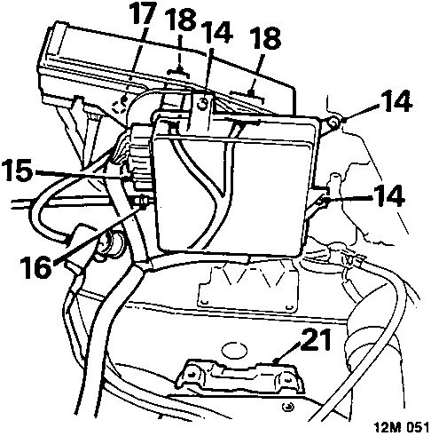
- Remove 3 nuts securing E.C.U. to mounting bracket.
- Disconnect multiplug from E.C.U.
- Release clip and disconnect vacuum pipe from E.C.U., remove E.C.U.
- Remove 2 bolts securing fuse box to valance.
- Disconnect 2 engine harness multiplugs from fuse box.
- Slacken nut on battery positive lead, release lead from terminal and move harness aside.
- Slacken 2 bolts securing battery tray support.
- Remove tray support.
Parts & tools for this job For Rover Coupé, Cabriolet & Tourer
- PARTEngine gasket setSearch: Rover Coupé, Cabriolet & Tourer engine gasket set
- TOOLTorque wrenchSearch: 3/8 inch torque wrench
- TOOLFeeler gauge setSearch: feeler gauge set
Links open Amazon search results in a new tab. As an Amazon Associate I earn from qualifying purchases.