
Engine and manual gearbox (page 3 of 5)
- Make
- Rover
- Model
- Coupé, Cabriolet & Tourer 200/400 Coupé, Cabriolet & Tourer Workshop Manual
- Section
- Repairs
Engine 2.0 T16Engine and manual gearbox · page 3 of 5
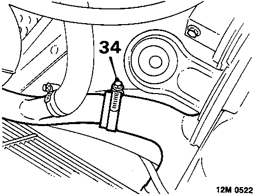
- Slacken clip and disconnect bottom hose from coolant rail.
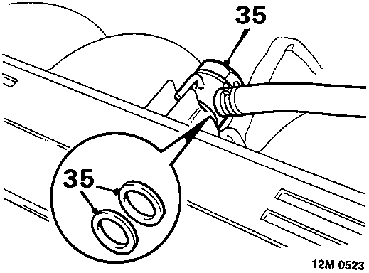
- Remove brake servo banjo bolt, collect 2 sealing washers.
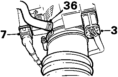
- Disconnect breather hose from throttle housing.
- Release multiplugs from throttle housing.
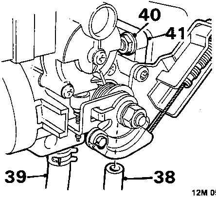
- Turbo models: Release turbocharger hose from throttle housing.
- Turbo models: Release clip and disconnect boost control valve hose from throttle housing. Remove bolt securing boost control valve solenoid to mounting bracket.
- Remove 4 nuts securing throttle housing to flexible mounting.
- Release throttle housing from studs and position aside.
- Disconnect purge hose from inlet manifold.
- Remove R.H. front headlamp for access to power steering union, see ELECTRICAL – Repairs.
- Position container beneath power steering pump.
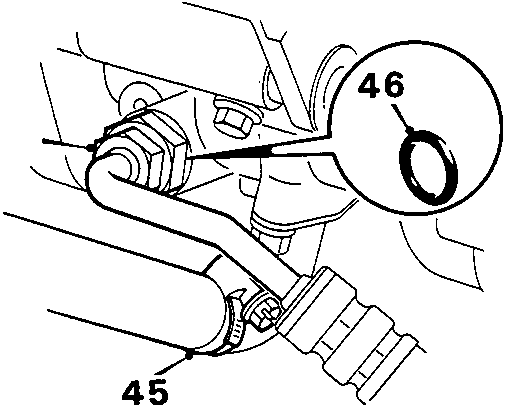
- Slacken clip, supply hose to power steering pump, disconnect hose.
- Using a 22 mm crow foot spanner, disconnect high pressure hose union from power steering pump, discard 'O' ring.
CAUTION: Plug the connections.
- Remove screw, power steering pipe to alternator.
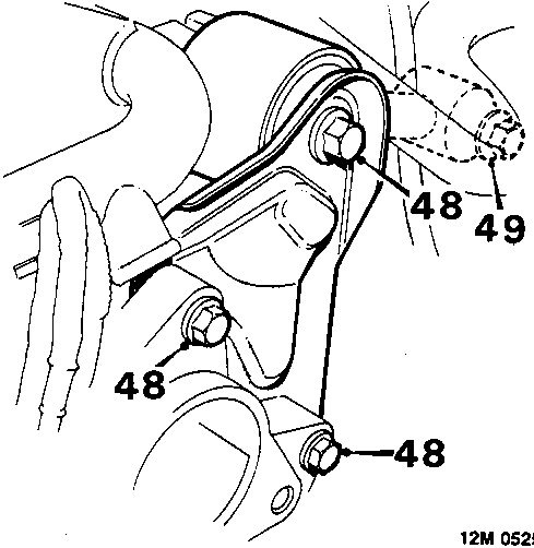
- Remove 3 bolts securing engine rear mounting plate to gearbox and mounting bracket, remove mounting plate.
- Remove bolt securing tie rod to bulkhead, remove tie rod.
- Remove R.H. front road wheel.
- Remove front L.H. tie rod, see SUSPENSION – Repairs.
Parts & tools for this job For Rover Coupé, Cabriolet & Tourer
- PARTEngine gasket setSearch: Rover Coupé, Cabriolet & Tourer engine gasket set
- TOOLTorque wrenchSearch: 3/8 inch torque wrench
- TOOLFeeler gauge setSearch: feeler gauge set
Links open Amazon search results in a new tab. As an Amazon Associate I earn from qualifying purchases.