
Engine and manual gearbox (page 4 of 5)
- Make
- Rover
- Model
- Coupé, Cabriolet & Tourer 200/400 Coupé, Cabriolet & Tourer Workshop Manual
- Section
- Repairs
Engine 2.0 T16Engine and manual gearbox · page 4 of 5
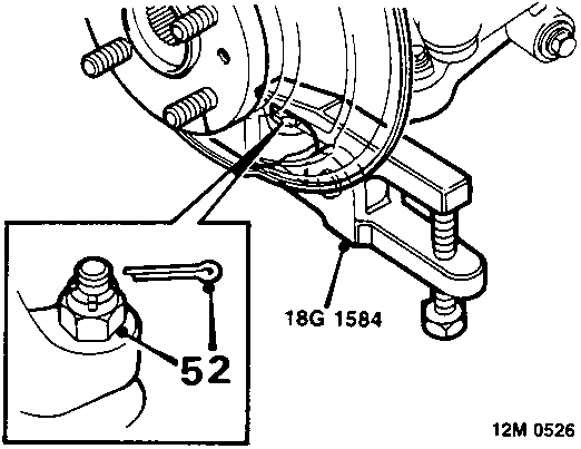
- Remove split pin from L.H. lower ball joint nut, remove nut.
- Break taper joint using tool 18G 1584.
- Repeat lower ball joint operations for R.H. side.
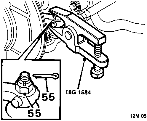
- Remove split pin from L.H. track rod ball joint nut, remove nut.
- Break taper joint using tool 18G 1584.
- Repeat track rod ball joint operations for R.H. side.
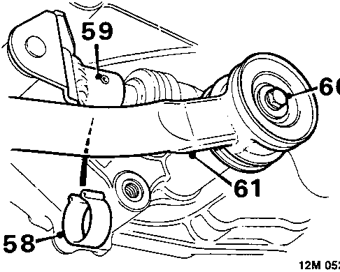
- Remove clip retaining selector rod roll pin.
- Using a punch, drive out selector rod roll pin.
- Remove bolt and disconnect gear change steady bar, collect 2 washers.
- Release steady bar and selector rod.
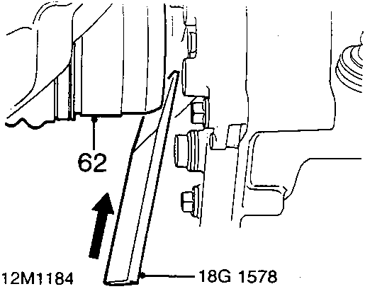
- Using tool 18G1578 release both drive shafts from differential.
CAUTION: Keep drive shafts horizontal to avoid damaging differential oil seal.
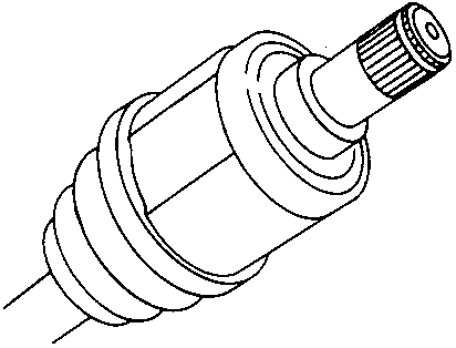
- Discard circlip from end of each drive shaft.
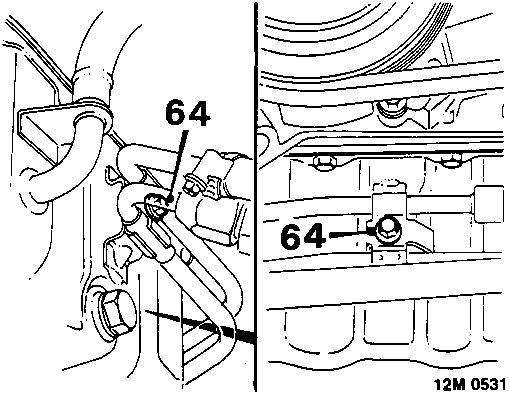
- Remove 2 bolts securing power steering pipes to sump brackets.
Parts & tools for this job For Rover Coupé, Cabriolet & Tourer
- PARTEngine gasket setSearch: Rover Coupé, Cabriolet & Tourer engine gasket set
- TOOLTorque wrenchSearch: 3/8 inch torque wrench
- TOOLFeeler gauge setSearch: feeler gauge set
Links open Amazon search results in a new tab. As an Amazon Associate I earn from qualifying purchases.