
Ignition coil
- Make
- Rover
- Model
- Coupé, Cabriolet & Tourer 200/400 Coupé, Cabriolet & Tourer Workshop Manual
- Section
- Repairs › Ignition coil
Modular engine management system - SPiIgnition coil
IGNITION COIL
Service Repair No. 18.20.32
Remove
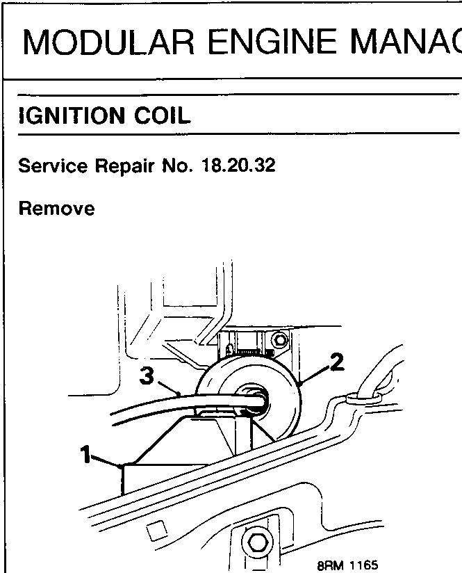
- Release and remove headlamp bulb access cover.
- Release cover from coil.
- Disconnect h.t. lead from coil.
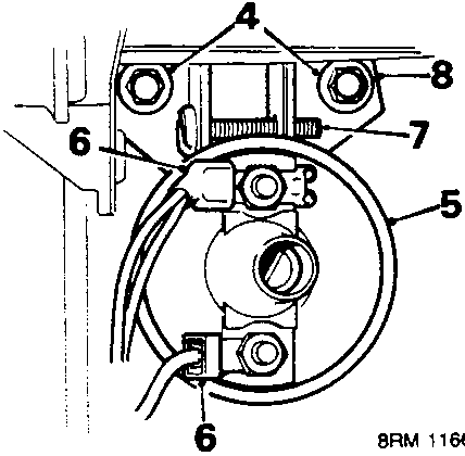
- Remove screws securing coil to body.
- Release coil from body.
- Disconnect 2 Lucars from coil and remove coil.
- Slacken screw from coil mounting bracket.
- Remove mounting bracket.
Refit
- Fit mounting bracket to coil and tighten bracket screw.
- Position coil and connect Lucars.
- Align coil to body, fit and tighten screws.
- Connect coil h.t. lead.
- Secure coil cover.
- Position and secure headlamp bulb access cover.
DISTRIBUTOR CAP AND ROTOR ARM
Service Repair No. Distributor – 18.20.18
Service Repair No. Rotor arm – 18.20.23
Remove
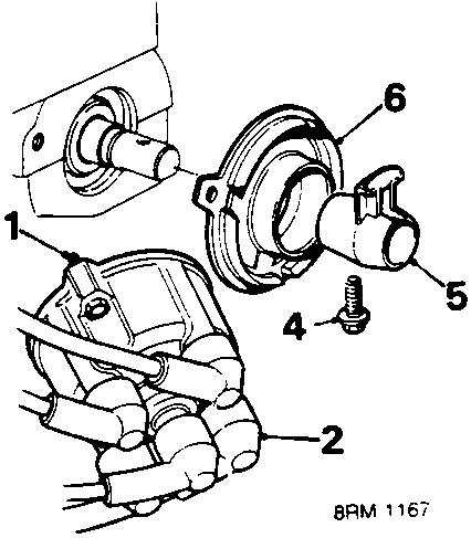
- Release 2 screws securing distributor cap.
- Move cap and h.t. leads aside.
- Rotate engine to align rotor arm for access to screw.
- Remove and discard screw securing rotor arm to camshaft.
- Remove rotor arm.
- Remove anti – flash shield.
Refit
- Fit anti – flash shield.
- Fit rotor arm to stud shaft.
- Fit new rotor arm screw and tighten to 10 Nm.
- Position distributor cap and leads.
- Fit screws securing distributor cap and tighten to 2 Nm.
Parts & tools for this job For Rover Coupé, Cabriolet & Tourer
- PARTSpark plugsSearch: Rover Coupé, Cabriolet & Tourer spark plugs
- TOOLSpark plug socketSearch: spark plug socket
- TOOLSpark plug gap toolSearch: spark plug gap tool
Links open Amazon search results in a new tab. As an Amazon Associate I earn from qualifying purchases.