
Remove
- Make
- Rover
- Model
- Coupé, Cabriolet & Tourer 200/400 Coupé, Cabriolet & Tourer Workshop Manual
- Section
- Repairs › Remove
Modular engine management system - SPiRemove
Service Repair No. 19.22.61
Remove
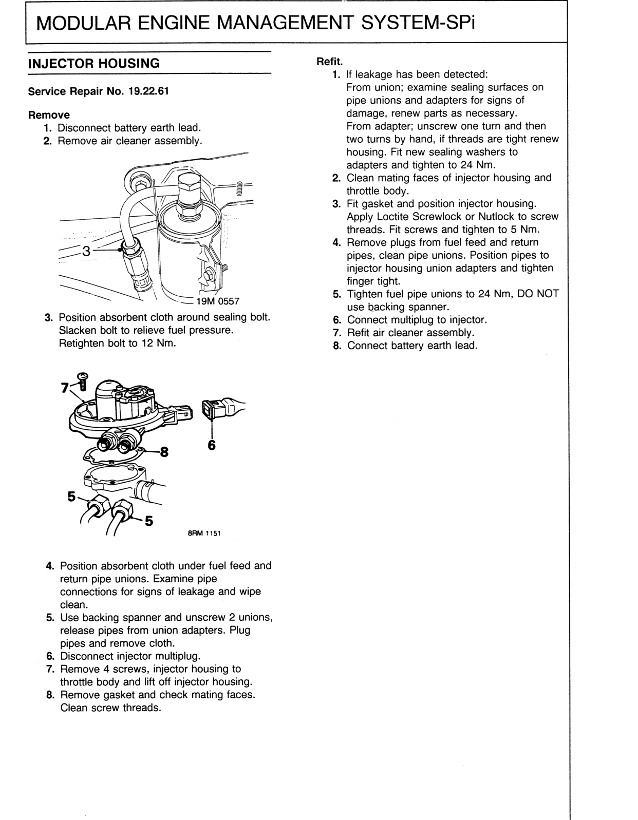
- Disconnect battery earth lead.
- Remove air cleaner assembly.
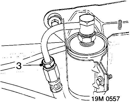
- Position absorbent cloth around sealing bolt. Slacken bolt to relieve fuel pressure. Retighten bolt to 12 Nm.
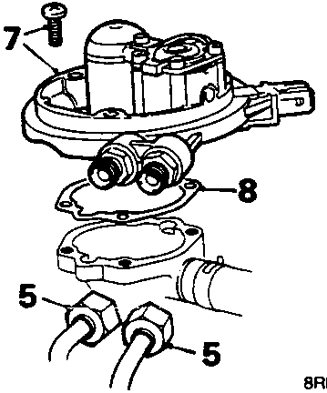
- Position absorbent cloth under fuel feed and return pipe unions. Examine pipe connections for signs of leakage and wipe clean.
- Use backing spanner and unscrew 2 unions, release pipes from union adapters. Plug pipes and remove cloth.
- Disconnect injector multiplug.
- Remove 4 screws, injector housing to throttle body and lift off injector housing.
- Remove gasket and check mating faces. Clean screw threads.
Refit.
- If leakage has been detected:
From union; examine sealing surfaces on pipe unions and adapters for signs of damage, renew parts as necessary.
From adapter; unscrew one turn and then two turns by hand, if threads are tight renew housing. Fit new sealing washers to adapters and tighten to 24 Nm. - Clean mating faces of injector housing and throttle body.
- Fit gasket and position injector housing. Apply Loctite Screwlock or Nutlock to screw threads. Fit screws and tighten to 5 Nm.
- Remove plugs from fuel feed and return pipes, clean pipe unions. Position pipes to injector housing union adapters and tighten finger tight.
- Tighten fuel pipe unions to 24 Nm, DO NOT use backing spanner.
- Connect multiplug to injector.
- Refit air cleaner assembly.
- Connect battery earth lead.
Original page
Parts & tools for this job For Rover Coupé, Cabriolet & Tourer
- PARTEngine gasket setSearch: Rover Coupé, Cabriolet & Tourer engine gasket set
- TOOLTorque wrenchSearch: 3/8 inch torque wrench
- TOOLFeeler gauge setSearch: feeler gauge set
Links open Amazon search results in a new tab. As an Amazon Associate I earn from qualifying purchases.